EasyManuals Logo

Danfoss VLT FC Series Service Guide

Danfoss VLT FC Series
370 pages
To Next Page IconTo Next Page
To Previous Page IconTo Previous Page
Page #268 background imageLoading...
Page #268 background image
130BF763.10
1
9
2
3
4
5
6
7
8
10
11
13
14
15
16
17
12
18
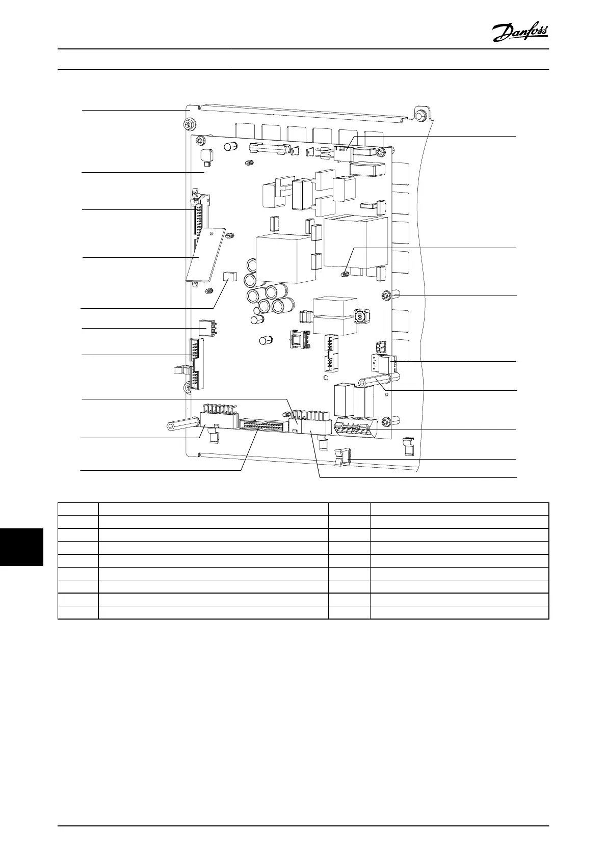
1 Power card mounting plate 10 MK103 (to gate drive card)
2 Power card 11 MK902 (to fan power card MK803)
3 MK102 (connector to control card ribbon cable) 12 Plastic stando
4 Current scaling card 13 Screw (T20)
5 MK100 (current scaling card connector) 14 MK106 (to brake temperature switch)
6 MK105 (to fan power card MK1200) 15 Metal stando (7 mm)
7 MK104 (signal test connector) 16 MK500 (to customer relays)
8 MK502 (to EMC relays) 17 Cable retaining clip
9 MK101 (to current sensors) 18 MK501 (to mixing fans)
Illustration 13.3 Power Card
E1h–E4h Drive Disassembly a...
VLT
®
FC Series, D1h–D8h, Da2/Db2/Da4/Db4, E1h–E4h, J8/J9
266 Danfoss A/S © 02/2019 All rights reserved. MG94A502
1313

Table of Contents

Other manuals for Danfoss VLT FC Series

Questions and Answers:

Question and Answer IconNeed help?

Do you have a question about the Danfoss VLT FC Series and is the answer not in the manual?

Danfoss VLT FC Series Specifications

General IconGeneral
CategoryDC Drives
SeriesVLT FC Series
Output Voltage0-100% of input voltage
Protection FeaturesOvervoltage, Undervoltage, Overcurrent, Short circuit, Overtemperature, Motor overload
Communication InterfacesCANopen, PROFIBUS, Ethernet
Cooling Methodliquid-cooled
Enclosure RatingIP20, IP21, IP55
Ambient Temperature-10°C to +40°C (14°F to 104°F) without derating

Related product manuals