EasyManuals Logo

Danfoss VLT FC Series Service Guide

Danfoss VLT FC Series
370 pages
To Next Page IconTo Next Page
To Previous Page IconTo Previous Page
Page #296 background imageLoading...
Page #296 background image
1
2
130BF838.10
4
5
7
6
3
9
10
8
11
12
13
14
15
16
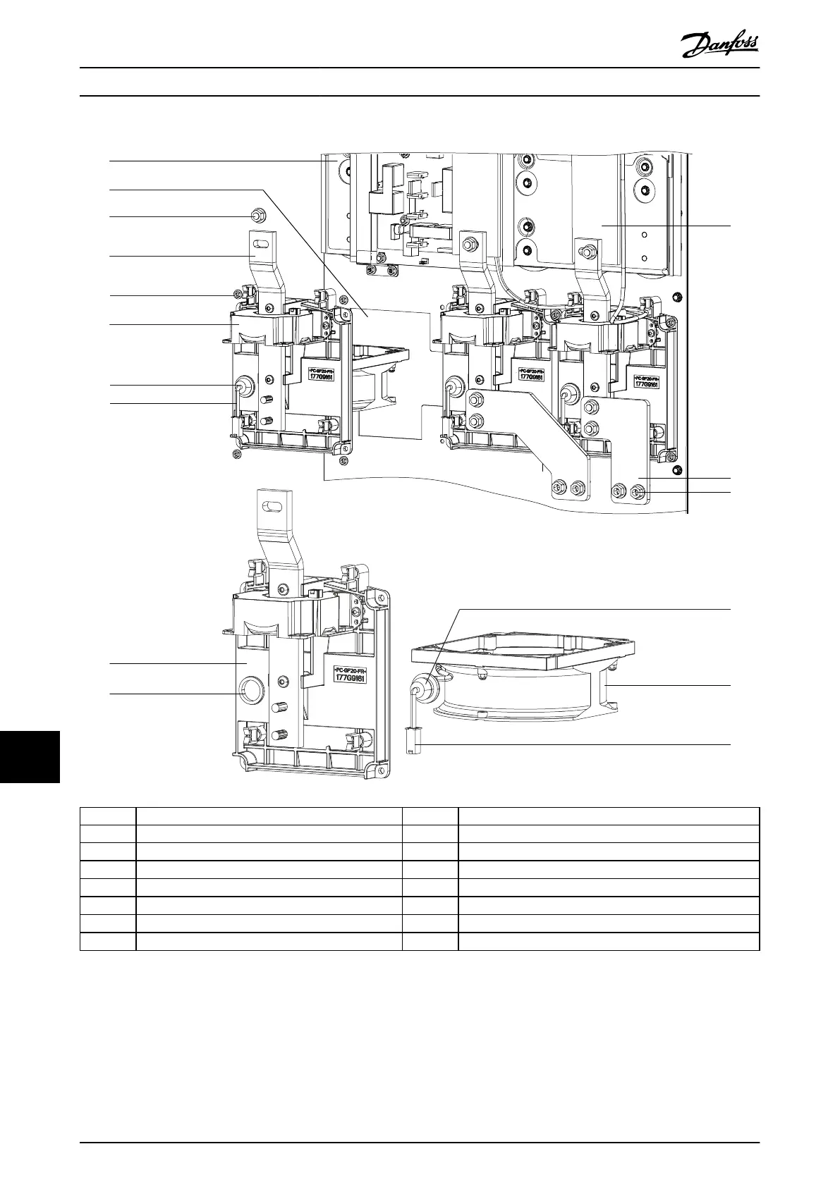
1 DC capacitor bank 9 Heat sink fan housing
2 Fan cutout 10 Hole for fan grommet
3 Nut (13 mm) 11 IGBT output busbar
4 Current sensor busbar 12 Right motor busbar
5 Nut (8 mm) 13 Nut (13 mm)
6 Current sensor 14 Fan grommet
7 Fan grommet (installed in fan housing) 15 Heat sink fan
8 Fan cable heat sink fan 16 Fan cable connector
Illustration 13.17 Heat Sink Fan (Shown with Left Motor Busbar Removed)
E1h–E4h Drive Disassembly a...
VLT
®
FC Series, D1h–D8h, Da2/Db2/Da4/Db4, E1h–E4h, J8/J9
294 Danfoss A/S © 02/2019 All rights reserved. MG94A502
1313

Table of Contents

Other manuals for Danfoss VLT FC Series

Questions and Answers:

Question and Answer IconNeed help?

Do you have a question about the Danfoss VLT FC Series and is the answer not in the manual?

Danfoss VLT FC Series Specifications

General IconGeneral
CategoryDC Drives
SeriesVLT FC Series
Output Voltage0-100% of input voltage
Protection FeaturesOvervoltage, Undervoltage, Overcurrent, Short circuit, Overtemperature, Motor overload
Communication InterfacesCANopen, PROFIBUS, Ethernet
Cooling Methodliquid-cooled
Enclosure RatingIP20, IP21, IP55
Ambient Temperature-10°C to +40°C (14°F to 104°F) without derating

Related product manuals