EasyManuals Logo

Danfoss VLT FC Series Service Guide

Danfoss VLT FC Series
370 pages
To Next Page IconTo Next Page
To Previous Page IconTo Previous Page
Page #302 background imageLoading...
Page #302 background image
130BF928.10
1
2
3
4
5
6
7
8
9
10
11
12
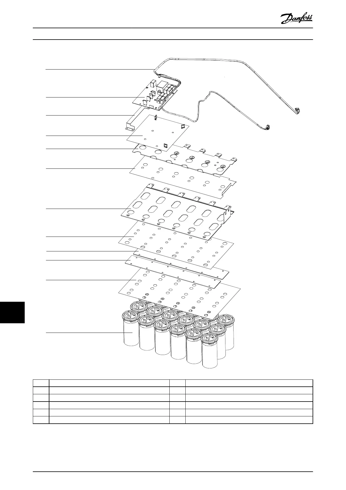
1 DC power cable (to power card shelf) 7 DC(-) bus plate
2 Balance/high frequency card 8 Insulator sheet 2
3 Ground bar 9 Midplate 1 (upper)
4 Insulator sheet (for balance/high frequency card) 10 Midplate 2 (lower)
5 DC(+) bus plate 11 Insulator sheet 3
6 Insulator sheet 1 12 DC capacitors
Illustration 13.21 E1h/E3h Capacitor Bank, 525–690 V AC (T7), 18 DC Capacitors
E1h–E4h Drive Disassembly a...
VLT
®
FC Series, D1h–D8h, Da2/Db2/Da4/Db4, E1h–E4h, J8/J9
300 Danfoss A/S © 02/2019 All rights reserved. MG94A502
1313

Table of Contents

Other manuals for Danfoss VLT FC Series

Questions and Answers:

Question and Answer IconNeed help?

Do you have a question about the Danfoss VLT FC Series and is the answer not in the manual?

Danfoss VLT FC Series Specifications

General IconGeneral
CategoryDC Drives
SeriesVLT FC Series
Output Voltage0-100% of input voltage
Protection FeaturesOvervoltage, Undervoltage, Overcurrent, Short circuit, Overtemperature, Motor overload
Communication InterfacesCANopen, PROFIBUS, Ethernet
Cooling Methodliquid-cooled
Enclosure RatingIP20, IP21, IP55
Ambient Temperature-10°C to +40°C (14°F to 104°F) without derating

Related product manuals