EasyManuals Logo

Danfoss VLT FC Series Service Guide

Danfoss VLT FC Series
370 pages
To Next Page IconTo Next Page
To Previous Page IconTo Previous Page
Page #316 background imageLoading...
Page #316 background image
1
130BF841.10
6
2
5
4
3
8
7
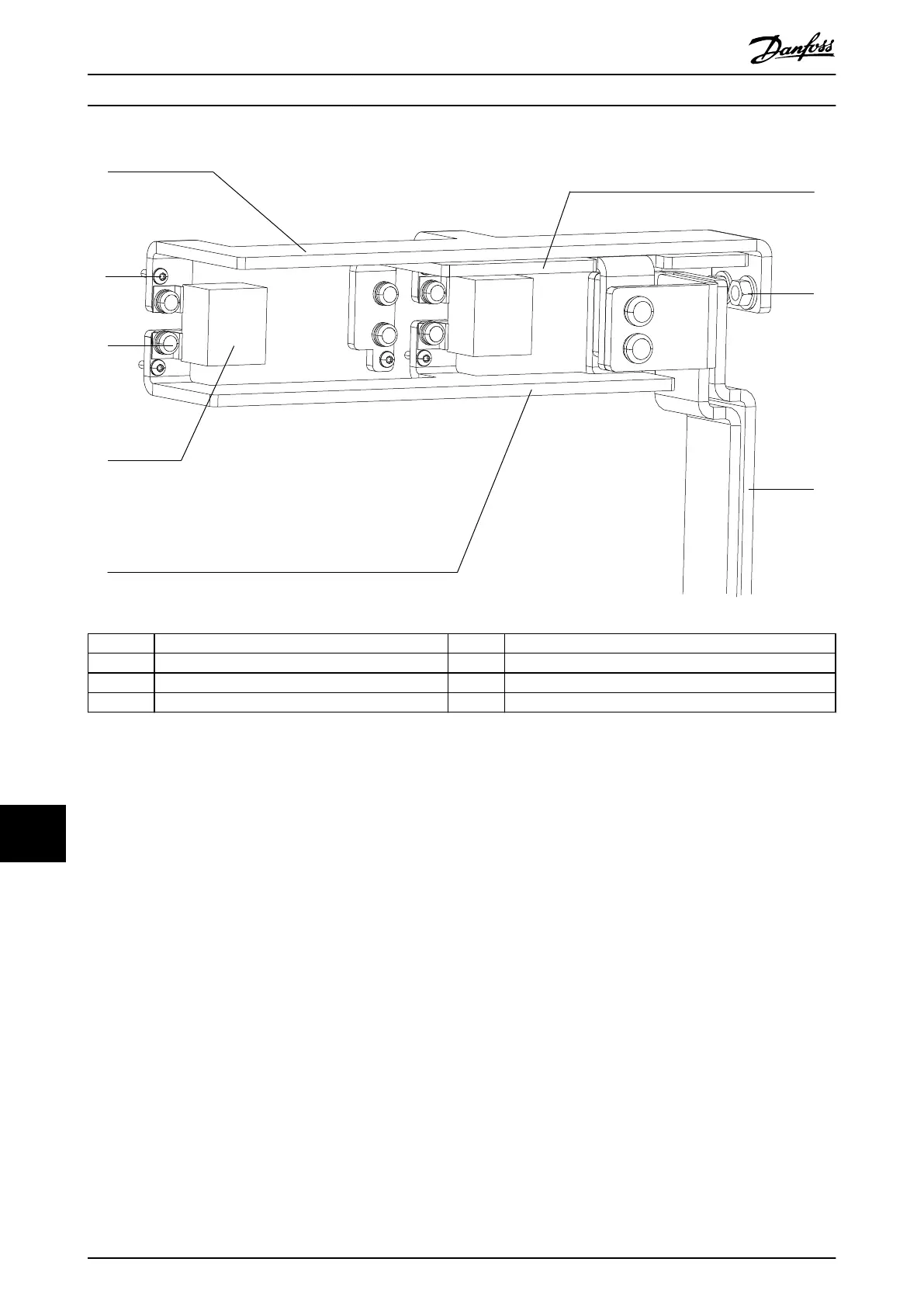
1 Top horizontal brake busbar 5 Bottom horizontal brake busbar
2 Thread-forming screw (T20) 6 Middle horizontal brake busbar
3 Screw (T40) 7 Nut (13 mm)
4 Snubber capacitor 8 Vertical brake busbars
Illustration 13.32 Horizontal Brake Busbars in E1h/E3h Drives
E1h–E4h Drive Disassembly a...
VLT
®
FC Series, D1h–D8h, Da2/Db2/Da4/Db4, E1h–E4h, J8/J9
314 Danfoss A/S © 02/2019 All rights reserved. MG94A502
1313

Table of Contents

Other manuals for Danfoss VLT FC Series

Questions and Answers:

Question and Answer IconNeed help?

Do you have a question about the Danfoss VLT FC Series and is the answer not in the manual?

Danfoss VLT FC Series Specifications

General IconGeneral
CategoryDC Drives
SeriesVLT FC Series
Output Voltage0-100% of input voltage
Protection FeaturesOvervoltage, Undervoltage, Overcurrent, Short circuit, Overtemperature, Motor overload
Communication InterfacesCANopen, PROFIBUS, Ethernet
Cooling Methodliquid-cooled
Enclosure RatingIP20, IP21, IP55
Ambient Temperature-10°C to +40°C (14°F to 104°F) without derating

Related product manuals