NOTE
Changing
this parameter affects parameters 1-22 Motor
Voltage to 1-25 Motor Frequency, 1-30 Stator Resistance, 1-33
Stator Leakage Reactance and 1-35 Main Reactance.
1-22 Motor Voltage (U_
m.n
)
Range: Function:
230/400 V [50-999 V] Enter motor voltage from nameplate
data.
1-23 Motor Frequency (f_
m.n
)
Range: Function:
50 Hz* [20-400 Hz] Enter motor frequency from nameplate
data.
1-24 Motor Current (I_
m.n
)
Range: Function:
M-type dependent* [0.01-100.00 A] Enter motor current from
nameplate
data.
1-25 Motor Nominal Speed (n_
m.n
)
Range: Function:
M-type Dependent* [100-9999 RPM] Enter motor nominal
speed
from nameplate
data.
1-29 Automatic Motor Tuning (AMT)
Option: Function:
Use AMT to optimize motor performance.
NOTE
This parameter cannot be changed while
motor runs.
1. Stop the frequency converter - make
sure
motor is at standstill
2.
Choose [2] Enable AMT
3. Apply start signal
- Via LCP: Press [Hand On]
- Or in Remote On mode: Apply start
signal on terminal 18
[0] * Off AMT function is disabled.
[2] Enable
AMT
AMT function starts running.
NOTE
To
gain optimum tuning of the frequency
converter, run AMT on a cold motor.
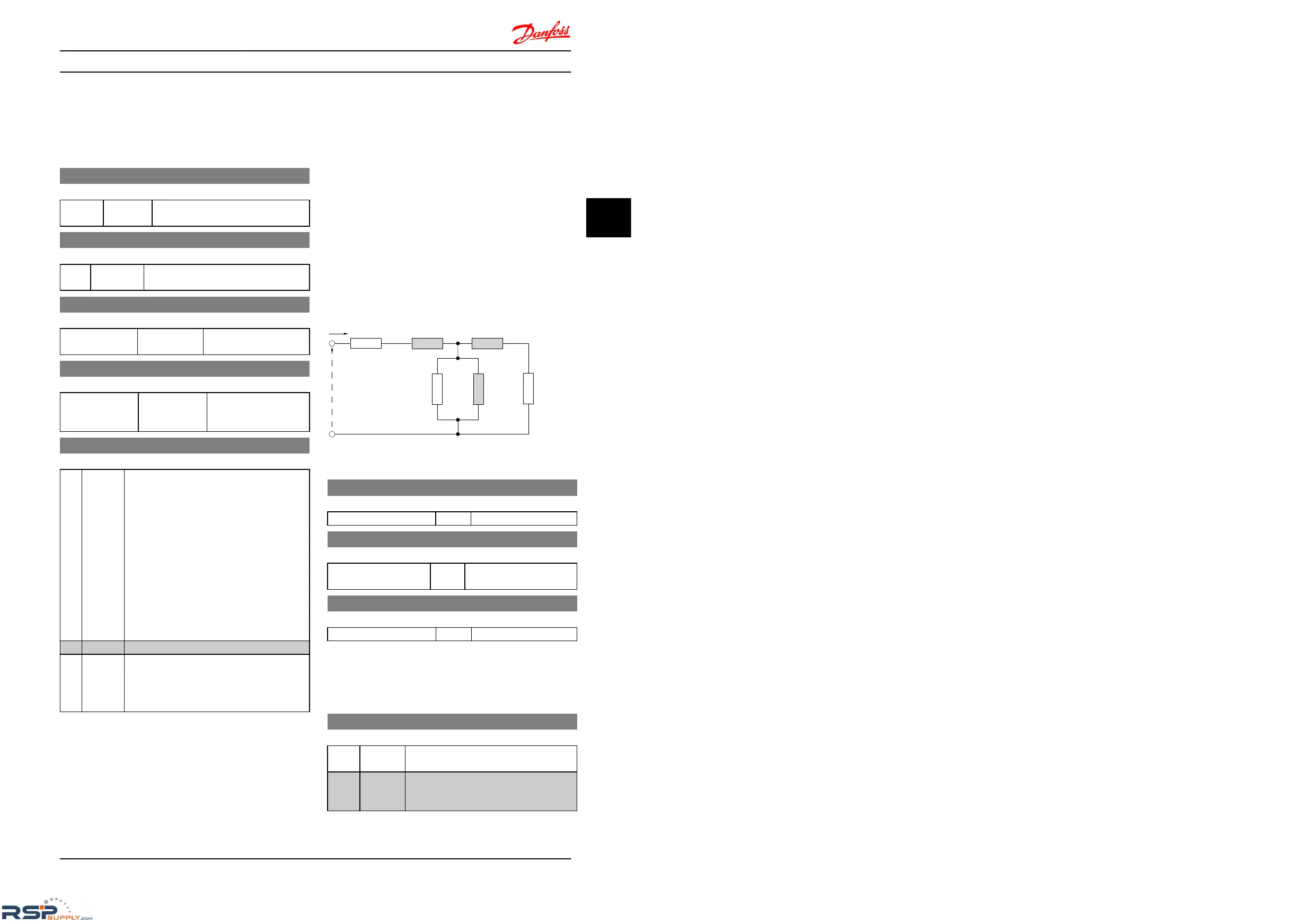
4.2.2 1-3* Adv. Motor Data
Adjust advanced motor data using one of these methods:
1.
Run AMT on cold motor. The frequency converter
measures value from motor.
2. Enter X
1
value manually. Obtain value from motor
supplier.
3. Use R
s
, X
1
, and X
2
default setting. The frequency
converter establishes setting based on motor
nameplate data.
NOTE
These
parameters cannot be changed while the motor
runs.
Illustration 4.1
1-30 Stator Resistance (R
s
)
Range: Function:
Depending on motor data* [Ohm] Set stator resistance value.
1-33 Stator Leakage Reactance (X
1
)
Range: Function:
Depending on motor
data*
[Ohm] Set stator leakage reactance
of
motor.
1-35 Main Reactance (X
2
)
Range: Function:
Depending on motor data* [Ohm] Set motor main reactance.
4.2.3 1-5* Load Independent Setting
This parameter group is for setting the load independent
motor
settings.
1-50 Motor Magnetization at Zero Speed
Range: Function:
This parameter enables different thermal
load
on motor when running at low speed.
100 %* [ 0-300%] Enter a percentage of rated magnetizing
current.
If setting is too low, motor shaft
torque may be reduced.
Parameter Descriptions
VLT
®
Micro Drive FC 51 Programming Guide
MG02C602 - VLT
®
is a registered Danfoss trademark
15
4 4

 Loading...


