4.10 Parameter Group 13: Smart Logic
4.10.1 13-** Programming Features
Smart Logic Control (SLC)is a sequence of user-defined
actions
(13-52 SL Controller Action [X]) executed by the SLC
when the associated user-defined event (13-51 SL Controller
Event [X]) is set to True.
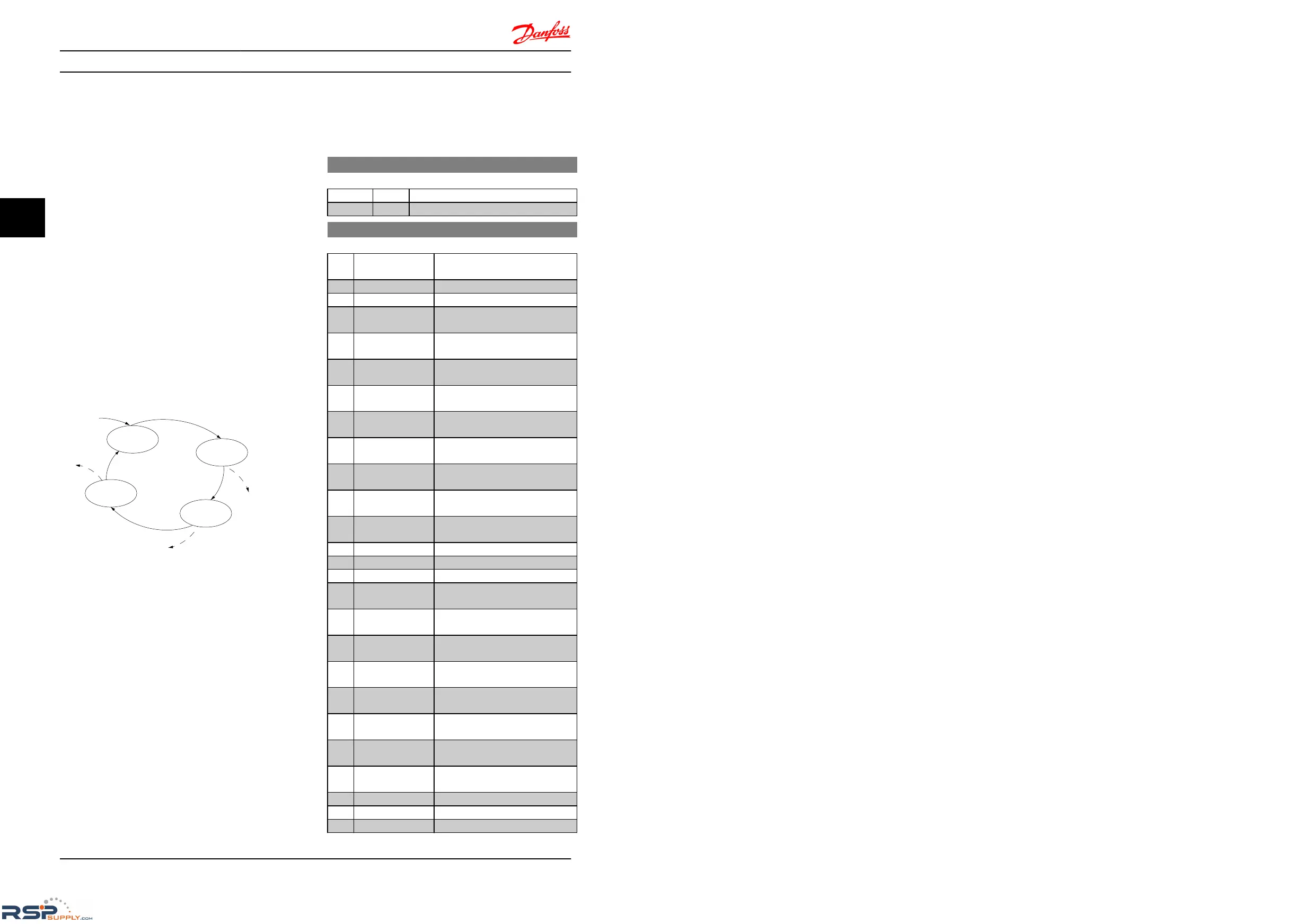
Events and actions are linked in pairs, meaning that when
an event is true, the linked action is carried out. After this
the next event is evaluated and its belonging action
carried out and so on. Only one event is evaluated at the
time.
If an event is evaluated as False, the SLC takes no action
during the scan interval and no other events are evaluated.
It is possible to programme from 1 to 20 events and
actions.
When the last event/action has been executed, the
sequence starts again from event/action [0].
Illustration 4.10 Example with Three Events/Actions
Starting and stopping the SLC
Start
the SLC by selecting [1] On in 13-00 SL Controller
Mode The SLC starts evaluating Event 0, and if this is
evaluated as TRUE, the SLC continues its cycle.
The SLC stops when the Stop Event, 13-02 Stop Event, is
TRUE. The SLC can also be stopped by selecting [0] Off in
13-00 SL Controller Mode.
To reset all SLC parameters select [1] Reset SLC in 13-03
Reset Smart Logic Controller and start programming from
scratch.
4.10.2 13-0* SLC Settings
Use SLC settings to activate, deactivate and reset the
Smart
Logic Control.
13-00 SL Controller Mode
Option: Function:
[0] * Off Function is disabled.
[1] On SLC is active.
13-01 Start Event
Option: Function:
Select input to activate Smart Logic
Control.
[0] False
Enters False
in logic rule.
[1] True
Enters True
in logic rule.
[2] Running
See parameter group 5-4*
Relays [5]
for description.
[3] InRange
See parameter group 5-4*
Relays [7]
for description.
[4] OnReference
See parameter group 5-4*
Relays [8]
for description.
[7] Out of Current
Range
See parameter group 5-4*
Relays [12]
for description.
[8] BelowILow
See parameter group 5-4*
Relays [13]
for description.
[9] AboveIHigh
See parameter group 5-4*
Relays [14]
for description.
[16] ThermalWarning
See parameter group 5-4*
Relays [21]
for description.
[17] MainsOutOfRange Mains voltage is outside the
specified
voltage range.
[18] Reversing
See parameter group 5-4*
Relays [25]
for description.
[19] Warning A warning is active.
[20] Alarm_Trip A trip alarm is active.
[21] Alarm_TripLock A trip lock alarm is active.
[22] Comparator 0 Use result of comparator 0 in logic
rule.
[23] Comparator 1 Use result of comparator 1 in logic
rule.
[24] Comparator 2 Use result of comparator 2 in logic
rule.
[25] Comparator 3 Use result of comparator 3 in logic
rule.
[26] LogicRule 0 Use result of logic rule 0 in logic
rule.
[27] LogicRule 1 Use result of logic rule 1 in logic
rule.
[28] LogicRule 2 Use result of logic rule 2 in logic
rule.
[29] LogicRule 3 Use result of logic rule 3 in logic
rule.
[33] DigitalInput_18 Use value of DI 18 in logic rule.
[34] DigitalInput_19 Use value of DI 19 in logic rule.
[35] DigitalInput_27 Use value of DI 27 in logic rule.
Parameter Descriptions
VLT
®
Micro Drive FC 51 Programming Guide
40 MG02C602 - VLT
®
is a registered Danfoss trademark
44

 Loading...


