4.4 Parameter Group 3: Reference/Ramps
4.4.1 3-** Reference/Ramps
Parameters for reference handling, definition of limitations,
and
configuration of the frequency converter's reaction to
changes
4.4.2 3-0* Reference Limits
Parameters for setting the reference unit, limits and ranges.
3-00 Reference Range
Option: Function:
Select the range of reference and feedback
signals.
[0] * Min to
Max
Reference setpoint ranges can have positive
values
only.
Select this if running in Process Closed Loop.
[1] -Max to
+Max
Ranges can have both positive and negative
values.
If
potentiometer is used to adjust motor running
in both direction, set reference range to –Max
Reference to Max Reference by par.=[1] Choose
hand on mode by LCP. Adjust the potentiometer
to minimum, the motor can run in anti-clockwise
with max speed. Then adjust the potentiometer
to maximum, the motor will ramp down to 0
and run clockwise with max speed.
3-02 Minimum Reference
Range: Function:
0.00* [-4999-4999] Enter value for minimum reference.
The sum of all internal and external
references are clamped (limited) to the
minimum reference value, 3-02 Minimum
Reference.
3-03 Maximum Reference
Range: Function:
Maximum Reference is adjustable in the
range
Minimum Reference -4999.
50.00* [-4999-4999] Enter value for Maximum Reference.
The
sum of all internal and external
references are clamped (limited) to the
maximum reference value, 3-03 Maximum
Reference.
4.4.3 3-1* References
Parameters for setting up the reference sources. Select the
preset
references for the corresponding digital inputs in
parameter group, 5-1* Digital Inputs.
3-10 Preset Reference
Option: Function:
Each parameter set-up contains 8 preset
references
which are selectable via 3
digital inputs or bus.
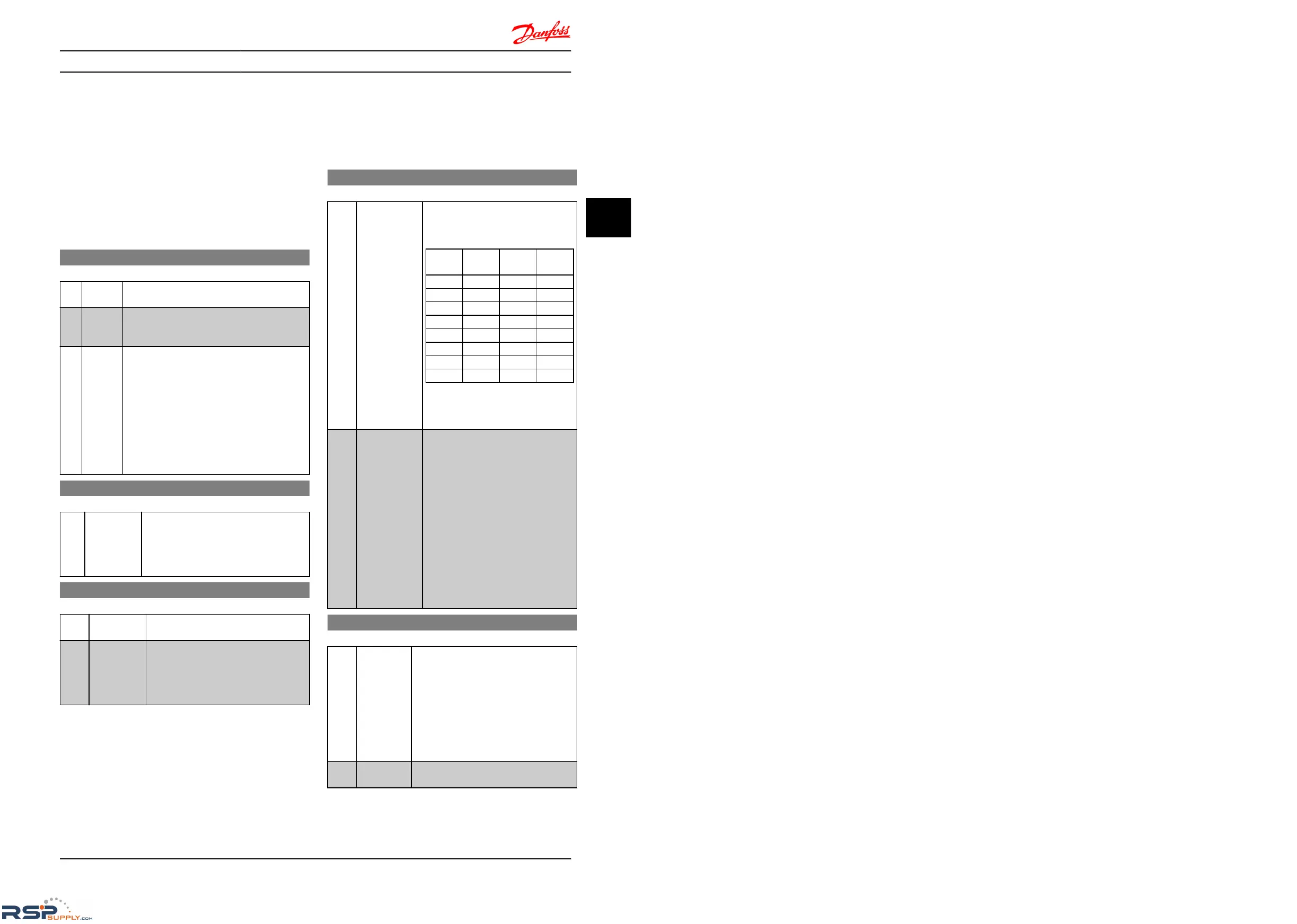
[18]
Bit2
[17]
Bit1
[16]
Bit0
[16]
Bit0
0 0 0 0
0 0 1 1
0 1 0 2
0 1 1 3
1 0 0 4
1 0 1 5
1 1 0 6
1 1 1 7
Table 4.2 Parameter Group 5-1* Digital
Inputs
Option [16], [17] and [18]
[0.00]
*
-100.00-100.00% Enter the different preset references
using
array programming.
Normally, 100% = value set in 3-03
Maximum Reference.
However, there are exceptions if 3-00
Reference Range is set to [0] Min - Max.
Example 1:
3-02 Minimum Reference is set to 20 and
3-03 Maximum Reference is set to 50. In
this case 0%=0 and 100%=50.
Example 2:
3-02 Minimum Reference is set to -70
and 3-03 Maximum Reference is set to
50. In this case 0%=0 and 100%=70.
3-11 Jog Speed [Hz]
Range: Function:
Jog speed is a fixed output speed and
overrules
the selected reference speed, see
parameter group 5-1* Digital Inputs option
[14].
If the motor is stopped while in jog mode,
the jog signal acts as a start signal.
Removing the jog signal makes the motor
run according to the selected configu-
ration.
5.0
Hz
[0.0-400.0
Hz]
Select speed to function as jog speed.
Parameter Descriptions
VLT
®
Micro Drive FC 51 Programming Guide
MG02C602 - VLT
®
is a registered Danfoss trademark
21
4 4

 Loading...


