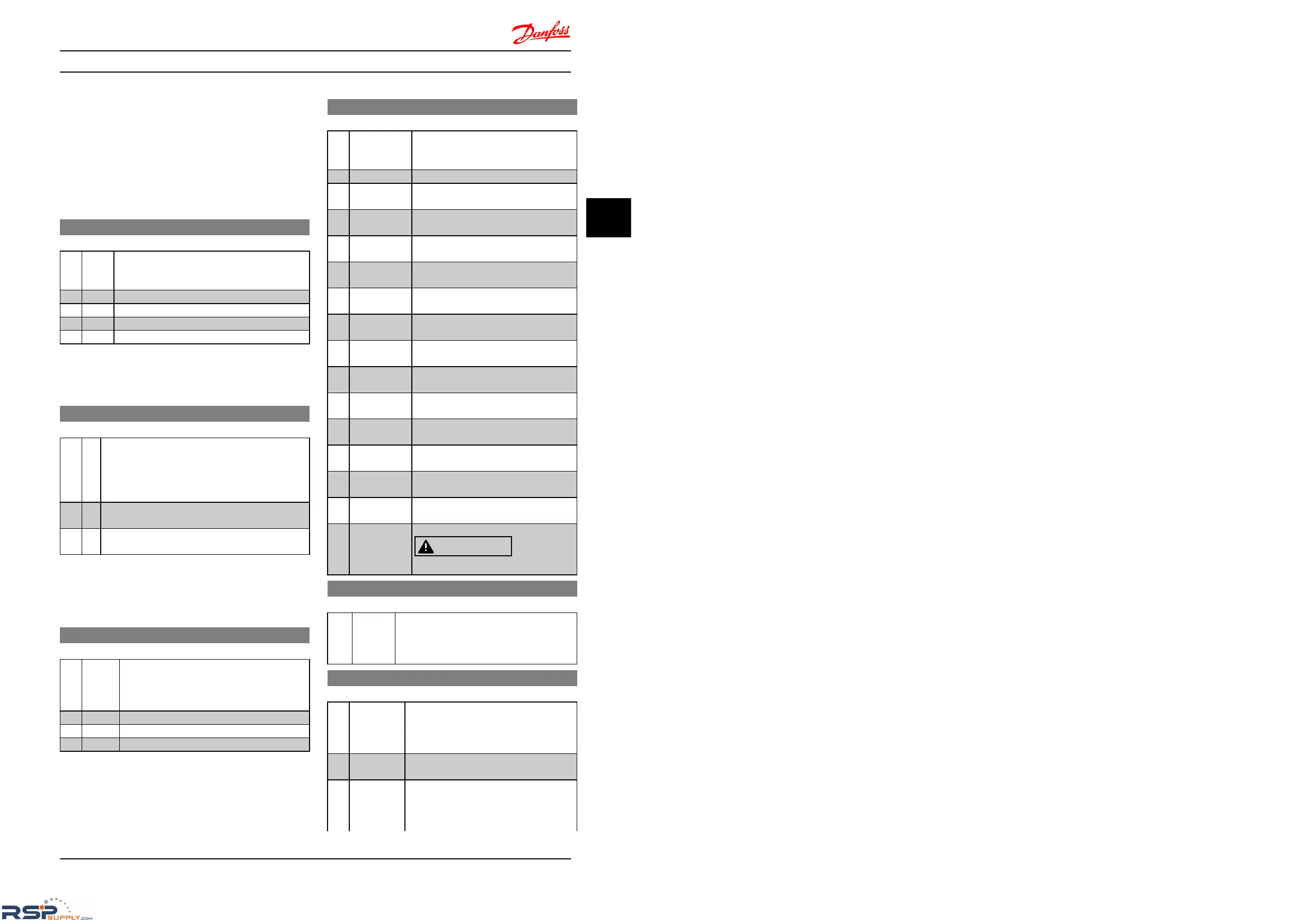
4.11 Parameter Group 14: Special Functions
4.11.1 14-** Special Functions
Parameter group for configuring special frequency
converter
functions.
4.11.2 14-0* Inverter Switching
14-01 Switching Frequency
Option: Function:
Select the switching frequency in order to
minimize
e.g. acoustic noise and power loss or
maximizing efficiency.
[0] 2 KHz
[1] * 4 KHz
[2] 8 KHz
[4] 16 KHz
NOTE
For
18.5 kW and 22 kW frequency converter, the option [4]
is not available.
14-03 Overmodulation
Option: Function:
This feature allows more accurate speed control near
and
over nominal speed (50/60 Hz). Another
advantage with overmodulation is the ability of
staying at a constant speed even though main is
dropping.
[0] Off Disables the overmodulation function to avoid torque
ripple
on the motor shaft.
[1] * On Connects the overmodulation function to obtain an
output
voltage up to 15% greater than mains voltage.
4.11.3 14-1* Mains Monitoring
This parameter group supplies functions for handling
imbalance
on mains.
14-12 Functions at Mains Imbalance
Option: Function:
Operation under severe mains imbalance
conditions
reduces drive lift time.
Select function to take place when severe mains
imbalance is detected.
[0] * Trip Frequency converter trips.
[1] Warning Frequency converter issues a warning.
[2] Disabled No action taken.
Parameters for configuring auto reset handling, special trip
handling
and control card self test or initialisation.
14-20 Reset Mode
Option: Function:
Select reset function after tripping. Once
reset,
the frequency converter can be
restarted.
[0] * Manual Reset Perform reset via [Reset] or digital inputs.
[1] AutoReset 1 Performs one automatic reset after
tripping.
[2] AutoReset 2 Performs two automatic resets after
tripping.
[3] AutoReset 3 Performs three automatic resets after
tripping.
[4] AutoReset 4 Performs four automatic resets after
tripping.
[5] AutoReset 5 Performs five automatic resets after
tripping.
[6] AutoReset 6 Performs six automatic resets after
tripping.
[7] AutoReset 7 Performs seven automatic resets after
tripping.
[8] AutoReset 8 Performs eight automatic resets after
tripping.
[9] AutoReset 9 Performs nine automatic resets after
tripping.
[10] AutoReset 10 Performs ten automatic resets after
tripping.
[11] AutoReset 15 Performs fifteen automatic resets after
tripping.
[12] AutoReset 20 Performs twenty automatic resets after
tripping.
[13] Infinite auto
reset
Performs an infinite number of automatic
resets
after tripping.
[14] Reset at
power-up
Trip-lock alarm can be reset at power up.
CAUTION
Motor may start without warning.
14-21 Automatic Restart Time
Range: Function:
10 s* [0-600 s] Enter time interval from trip to start of
automatic
reset function. This parameter is
active when 14-20 Reset Mode, is set to [1] to
[13] Automatic Reset.
14-22 Operation Mode
Option: Function:
Use this parameter for specifying normal
operation
or to initialize all parameters,
except 15-03 Power Ups, 15-04 Over Temps
and 15-05 Over Volts.
[0] * Normal
Operation
Frequency converter runs normal operation.
[2] Initialization Resets all parameters to default settings,
except
for 15-03 Power Ups, 15-04 Over
Temps and 15-05 Over Volts. Frequency
converter resets during next power-up.
Parameter Descriptions
VLT
®
Micro Drive FC 51 Programming Guide
MG02C602 - VLT
®
is a registered Danfoss trademark
45
4 4

 Loading...


