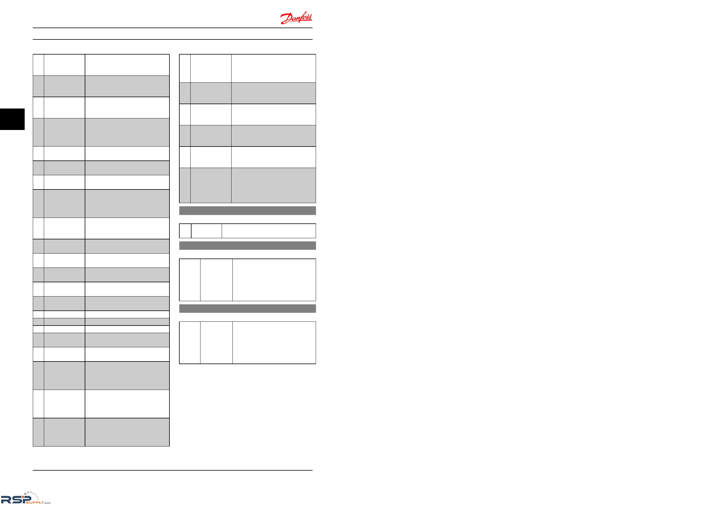
[22] Ready, No
Thermal
Warning
Frequency converter is ready for
operation and no over-temperature
warning is present.
[23] Remote Ready, No
Thermal
Warning
Frequency converter is ready for
operation in Auto mode, and no over-
temperature warning is present.
[24] Ready, Voltage OK Frequency converter is ready for
operation
and mains voltage is within
specified voltage range.
[25] Reverse Motor runs/is ready to run clockwise
when
logic = 0 and counter clockwise
when logic = 1. Output changes as
soon as reversing signal is applied.
[26] Bus OK Active communication (no time-out) via
serial
communication port.
[28] Brake, No Warn Brake is active, and no warnings are
present.
[29] Brake Ready/No
Fault
Brake is ready for operation, and no
faults
are present.
[30] Brake Fault (IGBT) Protects frequency converter if fault on
brake
modules is present. Use relay to
cut out main voltage from frequency
converter.
[32] Mech. Brake
Control
Enables control of external mechanical
brake,
see parameter group 2-2*
Mechanical Brake.
[36] Control Word Bit
11
Bit 11 in control word controls relay.
[41] Below Reference,
low
Reference is lower than set in 4-54
Warning
Reference Low.
[42] Above Reference,
high
Reference is higher than set in 4-55
Warning
Reference High.
[51] Local Reference
Active
[52] Remote Reference
Active
[53] No Alarm
[54] Start Cmd Active
[55] Running Reverse
[56] Drive in Hand
Mode
[57] Drive in Auto
Mode
[60] Comparator 0
See parameter group 13-1*
Comparators.
If comparator 0 is
evaluated as TRUE, output goes high.
Otherwise, it is low.
[61] Comparator 1
See parameter group 13-1*
Comparators.
If comparator 1 is
evaluated as TRUE, output goes high.
Otherwise, it is low.
[62] Comparator 2
See parameter group 13-1*
Comparators.
If comparator 2 is
evaluated as TRUE, output goes high.
Otherwise, it is low.
[63] Comparator 3
See parameter group 13-1*
Comparators.
If comparator 3 is
evaluated as TRUE, output goes high.
Otherwise, it is low.
[70] Logic Rule 0
See parameter group 13-4*
Logic Rules.
If Logic Rule 1 is evaluated as TRUE,
output goes high. Otherwise, it is low.
[71] Logic Rule 1
See parameter group 13-4*
Logic Rules.
If Logic Rule 2 is evaluated as TRUE,
output goes high. Otherwise, it is low.
[72] Logic Rule 2
See parameter group 13-4*
Logic Rules.
If Logic Rule 3 is evaluated as TRUE,
output goes high. Otherwise, it is low.
[73] Logic Rule 3
See parameter group 13-4*
Logic Rules.
If Logic Rule 3 is evaluated as TRUE,
output goes high. Otherwise, it is low.
[81] SL Digital Output
B
See 13-52
SL Control Action. When Smart
Logic Action [39] Set dig. out. A high is
executed, input goes high. When Smart
Logic Action [33] Set dig. out. A low is
executed, input goes low.
5-40 Function Relay
Option: Function:
[0] * No Operation Select function from available relay output
range.
5-41 On delay, Relay
Option: Function:
[0.01 s] * [0.00-600.00 s] Enter the delay of the relay cut-in time.
If
the Selected Event condition changes
before the On delay timer expires, the
relay output is unaffected. The function
to control the relay see 5-40 Function
Relay.
5-42 Off delay, Relay
Option: Function:
[0.01 s] * [0.00-600.00 s] Enter the delay of the relay cut-off
time.
If the Selected Event condition
changes before the off delay timer
expires, the relay output is unaffected.
The function to control the relay see
5-40 Function Relay.
4.6.5 5-5* Pulse Input
Set 5-15
Terminal 33 Digital Input to choice [32] pulse input.
Now terminal 33 handles a pulse input in the range from
Low frequency, 5-55 Terminal 33 Low Frequency, to 5-56
Terminal 33 High Frequency. Scale frequency input via 5-57
Terminal 33 Low Ref./Feedb. Value and 5-58 Terminal 33 High
Ref./Feedb. Value.
Parameter Descriptions
VLT
®
Micro Drive FC 51 Programming Guide
30 MG02C602 - VLT
®
is a registered Danfoss trademark
44

 Loading...


