13-10 Comparator Operand
Array [4]
Option: Function:
[2] Feedback Feedback in [Hz].
[3] MotorSpeed Motor speed in Hz.
[4] MotorCurrent Motor current in [A].
[6] MotorPower Motor power in either [kW] or [hp].
[7] MotorVoltage Motor voltage in [V].
[8] DCLinkVoltage DC-link voltage in [V].
[12] AnalogInput53 Expressed as actual value.
[13] AnalogInput60 Expressed as actual value.
[18] PulseInput33 Expressed as actual value.
[20] AlarmNumber Shows number of the alarm.
[30] CounterA Number of counts.
[31] CounterB Number of counts.
13-11 Comparator Operator
Array [4]
Option: Function:
Select operator to be used in comparison.
[0] Less Than <
Result of evaluation is True
if variable
selected in 13-10 Comparator Operand is
smaller than fixed value in 13-12
Comparator Value. Result is False if variable
selected in 13-10 Comparator Operand is
greater than fixed value in 13-12
Comparator Value.
[1] * Approxi-
mately
equals
≈
Result of evaluation is True if variable
selected in 13-10 Comparator Operand is
approximately equal to fixed value in 13-12
Comparator Value.
[2] Greater Than
>
Inverse logic of option [0].
13-12 Comparator Value
Array [4]
Range: Function:
0.0* [-9999-9999] Enter “trigger level” for variable monitored
by
this comparator.
4.10.4 13-2* Timers
Use the timer results to define an event (13-51
SL Controller
Action) or as boolean input in a logic rule (13-40 Logic Rule
Boolean 1, 13-42 Logic Rule Boolean 2 or 13-44 Logic Rule
Boolean 3).
When timer value has elapsed timer changes state from
False to True.
13-20 SLC Controller Timer
Array [3]
Range: Function:
0.0 s* [0.0-3600 s]
Enter value to define duration of the False
output
from programmed timer. A timer is
only False if it is started by an action and
until the given timer value has elapsed.
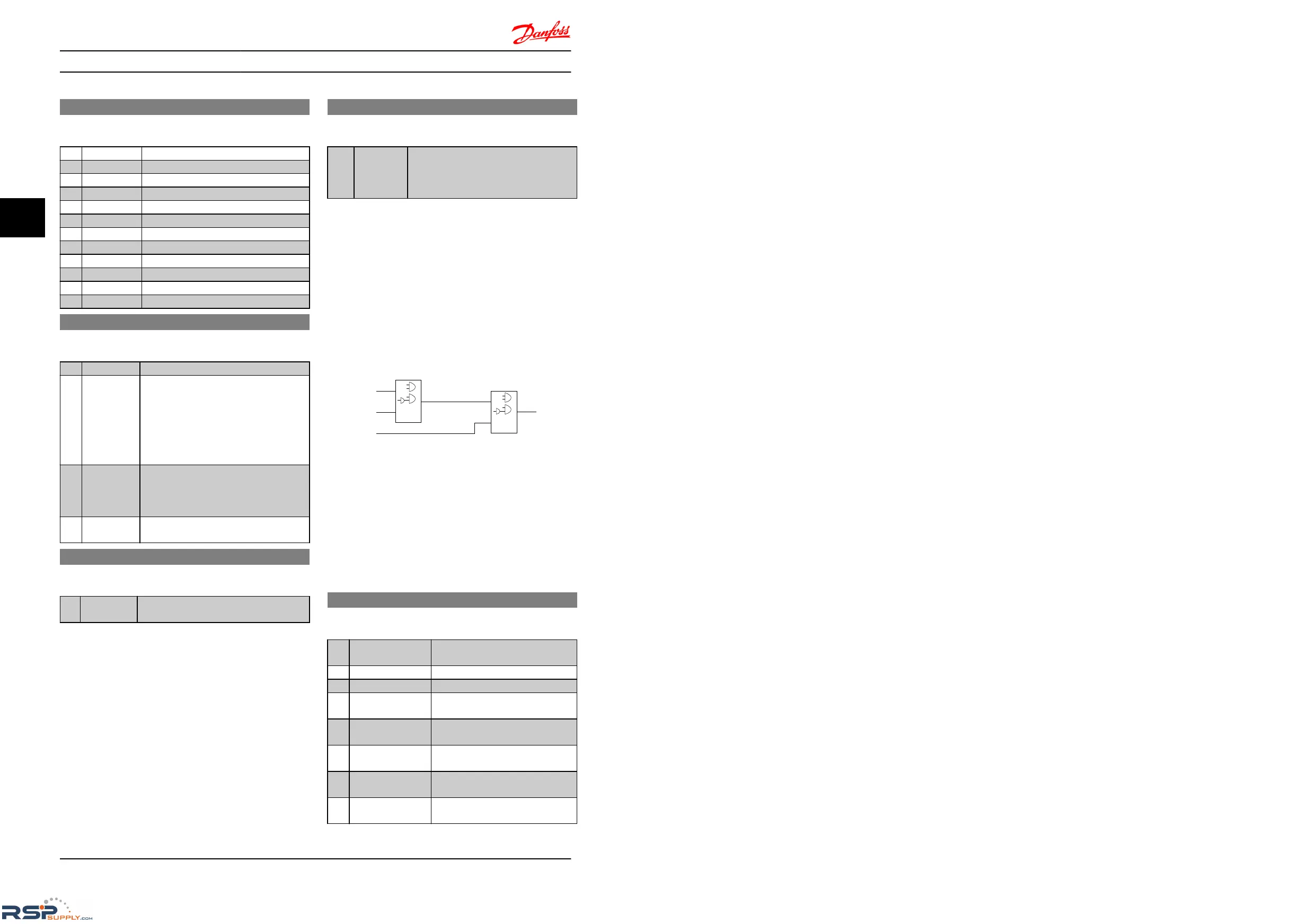
4.10.5 13-4* Logic Rules
Combine up to three boolean inputs (TRUE/FALSE inputs)
from
timers, comtors, digital inputs, status bits and events
using the logical operators AND, OR, and NOT. Select
boolean inputs for the calculation in LC-40 Logic Rule
Boolean 1, LC-42 Logic Rule Boolean 2 and LC-44 Logic Rule
Boolean 3. Define the operators used to logically combine
the selected inputs in LC-41 Logic Rule Operator 1 and
LC-43 Logic Rule Operator 2.
Illustration 4.12
Priority of calculation
The
results of LC-40 Logic Rule Boolean 1, LC-41 Logic Rule
Operator 1 and LC-42 Logic Rule Boolean 2 are calculated
first. The outcome (TRUE/FALSE) of this calculation is
combined with the settings of LC-43 Logic Rule Operator 2
and LC-44 Logic Rule Boolean 3, yielding the final result
(TRUE/FALSE) of the logic rule.
13-40 Logic Rule Boolean 1
Array [4]
Option: Function:
Select first boolean input for selected
logic
rule.
[0] * False
Enters False
in logic rule.
[1] True
Enters True
in logic rule.
[2] Running
See parameter group 5-4*
Relays [5]
for description.
[3] InRange
See parameter group 5-4*
Relays [7]
for description.
[4] OnReference
See parameter group 5-4*
Relays [8]
for description.
[7] Out of Current
Range
See parameter group 5-4*
Relays [12]
for description.
[8] BelowILow
See parameter group 5-4*
Relays [13]
for description.
Parameter Descriptions
VLT
®
Micro Drive FC 51 Programming Guide
42 MG02C602 - VLT
®
is a registered Danfoss trademark
44

 Loading...


