frequency converter. In this example it is less than a year
when compared with valves and constant speed.
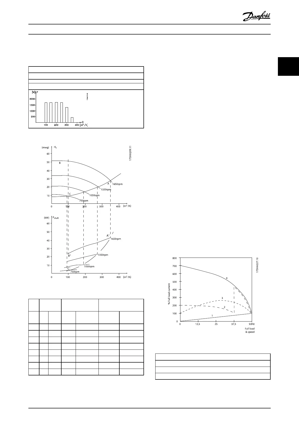
Energy savings
P
shaft
=P
shaft output
Flow distribution over 1 year
Table 2.4
Illustration 2.9
m
3
/h
Distri-
bution
Valve regulation Frequency converter
control
% Hours Power Consumpti
on
Power Consumptio
n
A
1
- B
1
kWh A
1
- C
1
kWh
350 5 438 42,5 18.615 42,5 18.615
300 15 1314 38,5 50.589 29,0 38.106
250 20 1752 35,0 61.320 18,5 32.412
200 20 1752 31,5 55.188 11,5 20.148
150 20 1752 28,0 49.056 6,5 11.388
100 20 1752 23,0 40.296 3,5 6.132
Σ 100 8760 275.064 26.801
Table 2.5
2.7.6 Better Control
If a frequency converter is used for controlling the flow or
pressure of a system, improved control is obtained.
A frequency converter can vary the speed of the fan or
pump, thereby obtaining variable control of flow and
pressure.
Furthermore, a frequency converter can quickly adapt the
speed of the fan or pump to new flow or pressure
conditions in the system.
Simple control of process (Flow, Level or Pressure) utilizing
the built in PID control.
2.7.7
Cos φ Compensation
Generally speaking, the VLT
®
Refrigeration Drive FCR 103
has a cos φ of 1 and provides power factor correction for
the cos φ of the motor, which means that there is no need
to make allowance for the cos φ of the motor when sizing
the power factor correction unit.
2.7.8 Star/Delta Starter or Soft-starter not
Required
When larger motors are started, it is necessary in many
countries to use equipment that limits the start-up current.
In more traditional systems, a star/delta starter or soft-
starter is widely used. Such motor starters are not required
if a frequency converter is used.
As illustrated in the figure below, a frequency converter
does not consume more than rated current.
Illustration 2.10
1 = VLT
®
Refrigeration Drive FCR 103
2 = Star/delta starter
3 = Soft-starter
4 = Start directly on mains
Table 2.6
Introduction
VLT
®
Refrigeration Drive Design Guide
MG16G102 - VLT
®
is a registered Danfoss trademark 19
2