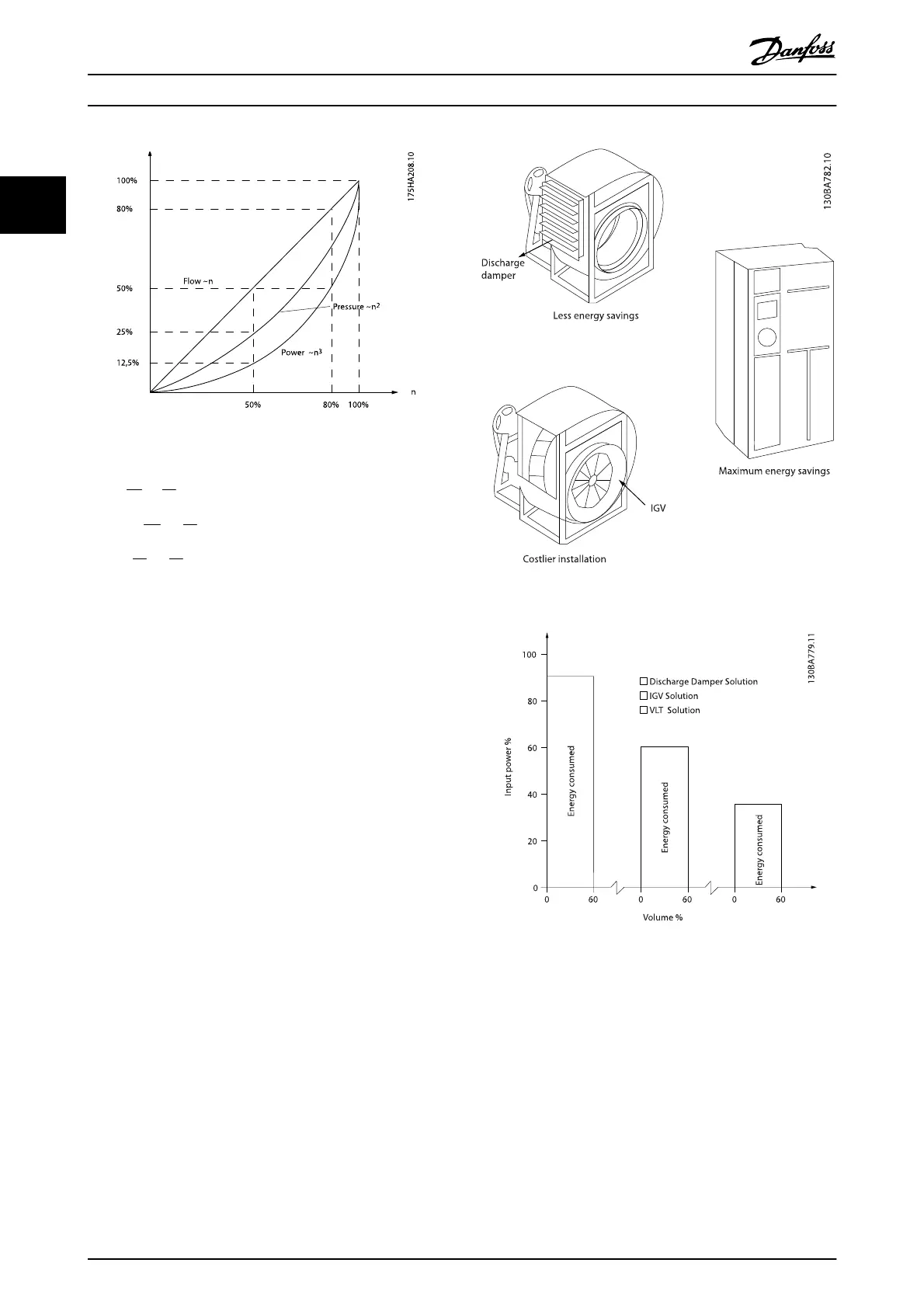
Illustration 2.6
Flow
:
Q
1
Q
2
=
n
1
n
2
Pressure
:
H
1
H
2
=
(
n
1
n
2
)
2
Power
:
P
1
P
2
=
(
n
1
n
2
)
3
2.7.4 Comparison of Energy Savings
The Danfoss frequency converter solution offers major
savings compared with traditional energy saving solutions.
This is because the frequency converter is able to control
fan speed according to thermal load on the system and
the fact that the frequency converter has a build-in facility
that enables the frequency converter to function as a
Building Management System, BMS.
The graph (Illustration 2.8) shows typical energy savings
obtainable with 3 well-known solutions when fan volume
is reduced to i.e. 60%.
As the graph shows, more than 50% energy savings can be
achieved in typical applications.
Illustration 2.7 The Three Common Energy Saving Systems.
Illustration 2.8 Discharge dampers reduce power consumption
somewhat. Inlet Guide Vans offer a 40% reduction but are
expensive to install. The Danfoss frequency converter solution
reduces energy consumption with more than 50% and is easy to
install.
2.7.5 Example with Varying Flow over 1
Year
The example below is calculated on the basis of pump
characteristics obtained from a pump datasheet.
The result obtained shows energy savings in excess of 50%
at the given flow distribution over a year. The pay back
period depends on the price per kWh and price of
Introduction
VLT
®
Refrigeration Drive Design Guide
18 MG16G102 - VLT
®
is a registered Danfoss trademark
2