Illustration 3.11 Connection to 24 V Backup Supplier (A5-C2).
3.1.9 Analog I/O option MCB 109
The Analog I/O card is supposed to be used in e.g. the
following cases:
•
Providing battery back-up of clock function on
control card
•
As general extension of analog I/O selection
available on control card, e.g. for multi-zone
control with three pressure transmitters
•
Turning frequency converter into de-central I/O
block supporting Building Management System
with inputs for sensors and outputs for operating
dampers and valve actuators
•
Support Extended PID controllers with I/Os for set
point inputs, transmitter/sensor inputs and
outputs for actuators.
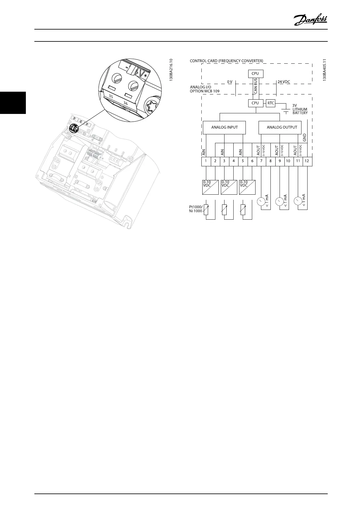
Illustration 3.12 Principle diagram for Analog I/O mounted in
frequency converter.
Analog I/O configuration
3 x Analog Inputs, capable of handling following:
•
0 - 10 V DC
OR
•
0-20 mA (voltage input 0-10 V) by mounting a
510 Ω resistor across terminals (see NOTE)
•
4-20 mA (voltage input 2-10 V) by mounting a
510 Ω resistor across terminals (see NOTE)
•
Ni1000 temperature sensor of 1000 Ω at 0° C.
Specifications according to DIN43760
•
Pt1000 temperature sensor of 1000 Ω at 0° C.
Specifications according to IEC 60751
3 x Analog Outputs supplying 0-10 V DC.
Drive Selection
VLT
®
Refrigeration Drive Design Guide
42 MG16G102 - VLT
®
is a registered Danfoss trademark
3