NOTE
Note the values available within the different standard
groups of resistors:
E12: Closest standard value is 470 Ω, creating an input of
449.9 Ω and 8.997 V.
E24: Closest standard value is 510 Ω, creating an input of
486.4Ω and 9.728 V.
E48: Closest standard value is 511 Ω, creating an input of
487.3 Ω and 9.746 V.
E96: Closest standard value is 523 Ω, creating an input of
498.2 Ω and 9.964 V.
Analog inputs - terminal X42/1-6
Parameter group for read out: 18-3*. See also VLT
®
Refrigeration Drive FCR 103 Programming Guide, MG11C.
Parameter groups for set-up: 26-0*, 26-1*, 26-2* and 26-3*.
See also VLT
®
Refrigeration Drive FCR 103 Programming
Guide, MG11CXYY.
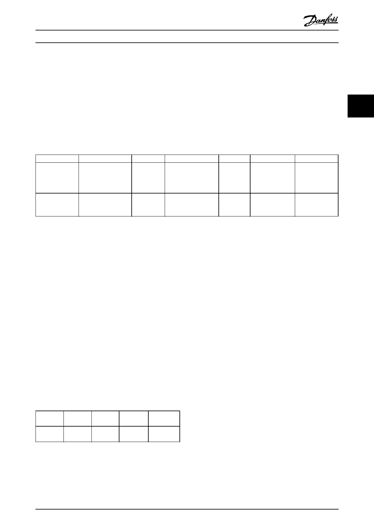
3 x Analog inputs Operating range Resolution Accuracy Sampling Max load Impedance
Used as
temperature
sensor input
-50 to +150 °C 11 bits -50 °C
±1 Kelvin
+150 °C
±2 Kelvin
3 Hz - -
Used as
voltage input
0 - 10 V DC 10 bits
0.2% of full
scale at cal.
temperature
2.4 Hz
± 20 V
continuously
Approximately
5 k
Ω
Table 3.7
When used for voltage, analog inputs are scalable by
parameters for each input.
When used for temperature sensor, analog inputs scaling is
preset to necessary signal level for specified temperature
span.
When analog inputs are used for temperature sensors, it is
possible to read out feedback value in both °C and °F.
When operating with temperature sensors, maximum cable
length to connect sensors is 80 m non-screened / non-
twisted wires.
Analog outputs - terminal X42/7-12
Parameter group for read out and write: 18-3*. See also
VLT
®
Refrigeration Drive FCR 103 Programming Guide,
MG16H
Parameter groups for set-up: 26-4*, 26-5* and 26-6*. See
also VLT
®
Refrigeration Drive FCR 103 Programming Guide,
MG16H
3 x Analog
outputs
Output
signal level
Resolution Linearity Max load
Volt 0-10 V DC 11 bits 1% of full
scale
1 mA
Table 3.8
Analog outputs are scalable by parameters for each
output.
The function assigned is selectable via a parameter and
have same options as for analog outputs on control card.
For a more detailed description of parameters, refer to the
VLT
®
Refrigeration Drive FCR 103 Programming Guide,
MG11C.
Real-time clock (RTC) with back-up
The data format of RTC includes year, month, date, hour,
minutes and weekday.
Accuracy of clock is better than ± 20 ppm at 25 °C.
The built-in lithium back-up battery lasts on average for
minimum 10 years, when frequency converter is operating
at 40 °C ambient temperature. If battery pack back-up fails,
analog I/O option must be exchanged.
Drive Selection
VLT
®
Refrigeration Drive Design Guide
MG16G102 - VLT
®
is a registered Danfoss trademark 43
3