Note, for connection of screen, refer to Illustration 3.13.
Instructions:
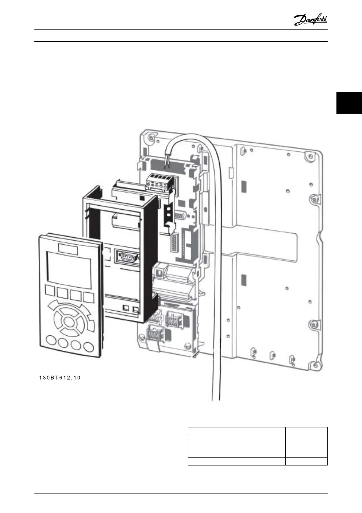
- Remove LCP panel from the FC 103
- Remove the frame located beneath and discard
- Push the option into place. Two positions are
possible, with cable terminal facing either up or
down
- Push the fieldbus option adaptor frame for the FC
103 into place
- Replace the LCP and attach cable
- On A1 and A2 enclosures with cable terminal
facing up: Fasten the cable onto the de-coupling
plate (the FC 103 top surface has pre-drilled
threaded holes for attaching the de-coupling
plate to the unit).
Illustration 3.15
Note, for connection of screen, refer to the graphic in
3.1.10 The LonWorks Option
The LCP can be moved to the front of a cabinet by using
the remote built-in kit. The enclosure is the IP66. The
fastening screws must be tightened with a torque of max.
1Nm.
Enclosure IP66 front
Max. cable length between and unit
3 m
8 m for option
130B1129
Communication std RS-485
Table 3.10 Technical Data
Drive Selection
VLT
®
Refrigeration Drive Design Guide
MG16G102 - VLT
®
is a registered Danfoss trademark 45
3