3.1.15 IP 21/Type 1 Enclosure Kit
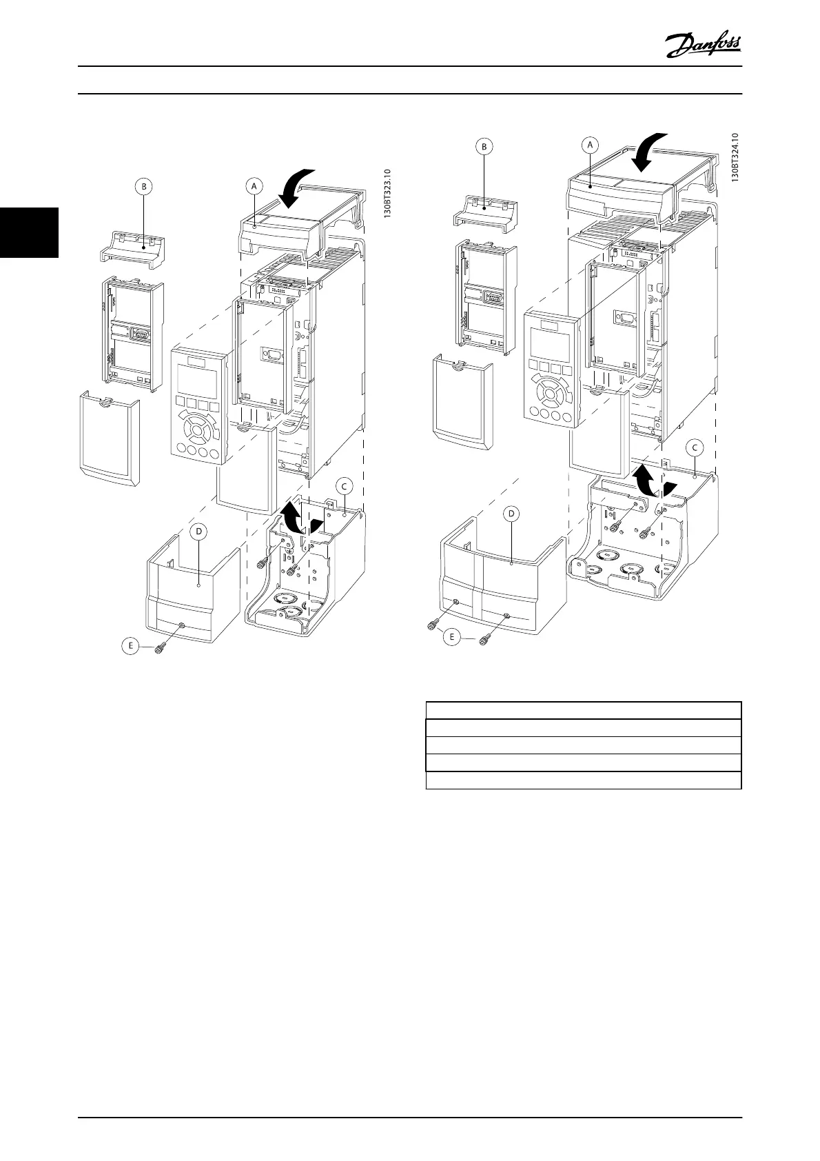
Illustration 3.24 A2 Enclosure
Illustration 3.25 A3 Enclosure
ATop cover
BBrim
C Base part
D Base cover
EScrew(s)
Table 3.12
Place the top cover as shown. If an A or B option is used
the brim must be fitted to cover the top inlet. Place the
base part C at the bottom of the frequency converter and
use the clamps from the accessory bag to correctly fasten
the cables. Holes for cable glands:
Size A2: 2x M25 and 3xM32
Size A3: 3xM25 and 3xM32
Drive Selection
VLT
®
Refrigeration Drive Design Guide
48 MG16G102 - VLT
®
is a registered Danfoss trademark
3