VLT
®
2800 Series
Programming
Bit 05, ON 3/OFF 3:
Bit 05 = ’0’ means that Bit 02 in the control word = ’1’.
Bit 05 = ’1’ means that Bit 02 in the control word = ’0’.
B
it 06, Start enab le/start disable:
Bit 06 = ’1’ after reset of a trip, after activation of OFF2
or OFF3 and after connect i on of ma ins voltage. Start
disable is reset by setting Bit 00 in the control word
to ’0’, and Bit 01, 02 and 10 are set to ’1’.
B
it 07, Warning:
See description under Status word according
to FC protocol.
B
it 08, Speed:
See description under Status word according
to FC protocol.
B
it 09, No w arning/warning:
See description under Status word according
to FC protocol.
B
it 10, Speed ≠ ref/speed = ref.:
See description under Status word according
to FC protocol.
B
it 11, Runn ing/not running:
See description under Status word according
to FC protocol.
B
it 13, Voltage warning high/low:
See description under Status word according
to FC protocol.
B
it 14, Current limit:
See description under Status word according
to FC protocol.
B
it 15, Thermal warning:
See description under Status word according
to FC protocol.
■ Serial communication reference
The serial communication reference is transferred to
the frequency converter as a 16-bit word. Th
evalueis
transferred in whole numbers 0 - ±32767 ( ± 200%).
16384 (4000 Hex) corresponds to 100%.
The serial communicati on reference has the following
format: 0-16384 (4000 Hex)
0-100% (Par. 204
Minimum ref. - Par. 205 Maximum ref.).
It is possible to change the direction of rotation via the
serial reference. This is done by converting the binary
reference value to 2’ complement. See example.
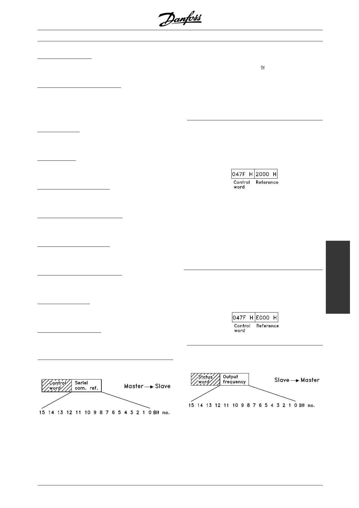
E
xample - Control word and serial communication ref.:
The frequency converter is to receive a start
command and the reference is to be set to 50%
(2000 Hex) of the reference range.
Control word = 047F Hex ⇒ Start command.
Reference = 2000 Hex ⇒ 50% reference.
The frequency converter is to receive a start
command and the reference is to be set to -50%
(-2000 Hex) of the reference range.
The reference value is first converted to 1’ complement,
and then 1 is adde d bina r ily to ob tain 2’ complement:
2000 Hex 0010 0000 0000 0000 0000
1’ complement 1101 1111 1111 1111 1111
+1
2’ complement 1110 0000 0000 0000 0000
Control word = 047F Hex ⇒ Start command.
Reference = E000 Hex ⇒ -50% referenc e.
■ Present output frequency
The value of the frequenc y converter’s present output
frequency is transferred as a 16-bit w ord. T
he value is
transferred as whole numbers 0 - ±32767 (±200%).
16384 (4000 Hex) corresponds to 100%.
MG.28.E9.02 - VLT is a registered Danfoss trademark
117
 Loading...


