VLT
®
2800 Series
Function:
In these parameters 302-307 Digital inputs it is possible
to choose between the different enabled functions
related to the digital inputs (terminals 18-33) .
Description of choice:
No operat ion is selected if the frequency converter is
not to react to signals transmitted to the terminal.
Reset resets the frequency converter after an
alarm; however, a few alarms cannot be reset
(trip locked) without first disconnecting the mains
supply and reconnecting it. See table under List
of warnings and alarms. Reset is activated on
the leading edge of the signal.
Coasting stop inverse is used for making the frequency
converter "let go" of the motor immediately ( output
transistors are "turned off"), which me ans that the motor
runs freely to stop. Logic ’0’ leadstocoastingtostop.
Reset and coasting inverse are used to activate
motor coast simultaneously with reset. Logical
’0’ me ans motor coast stop and reset. Reset
is activated on the falling edge.
Quick stop inverse is used for act ivating the quick-stop
ramp down set in parameter 212 Quick stop
ramp-down time. Logic ’0’ leads to quick stop.
DC-braking inverse is used for stopping the motor by
energizing it w ith a DC voltage for a given time, see
parameters 126, 127 and 132 DC brak e. Please note
that this function is only act ive if the value i
n parameter
126 DC braking time and 132 DC brake voltage is
different from 0. Logic ’0’ leads to DC braking.
Stop inverse, a logic ’0’ means that the motor spee d
is ramped down to stop via the selected
ramp.
None of the stop commands me ntioned
above are to be used as repair switches.
Note that the frequency converter has more
voltage inp uts than L1, L2 and L3
when the DC bus
terminals are used. Check that all voltage inputs are
disconnected an d that the pres cribed time (4 mins.)
has passed before repa ir w
ork is commenced.
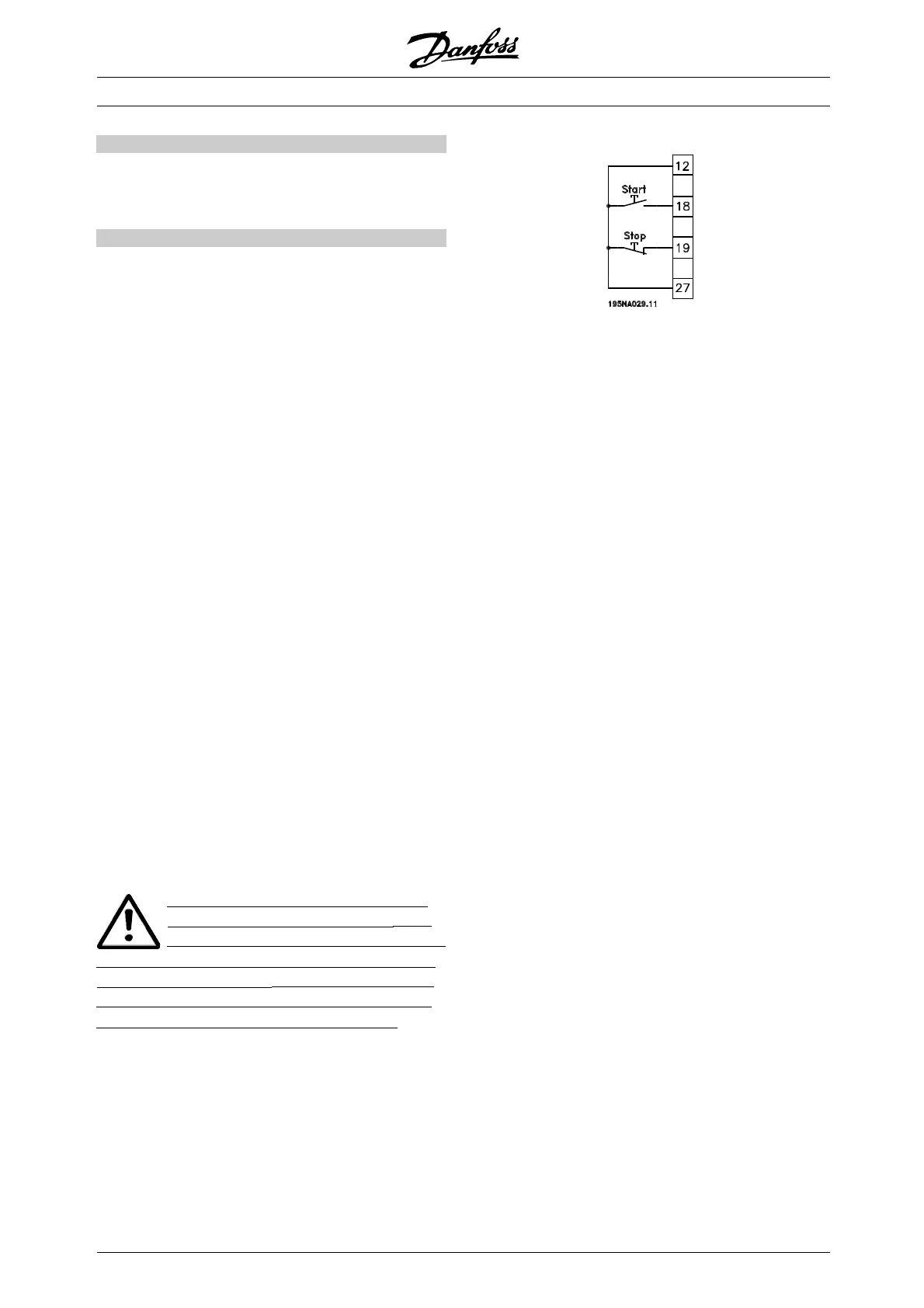
Start is selected if a start
/stop command is required.
Logic ’1’ = start, logic ’0’ =stop.
Latched start, if a pulse is applied for min. 14 ms,
the frequency converter will start the motor, provided
no stop command has been given. The motor can
be stopped by briefly activating Stop inverse.
Reversing is used for changing the direct ion of
rotation of the m otor shaft. Logic ’0’ will not lead
to reversing. Logic ’1’ will lead to reve rsing. The
reverse signal only changes the direct ion of rotation,
it does not activate the start. Is not active at Process
regulation, closed loop . See also parameter 200
Output frequency range/direct ion.
Reversing and start i s used for start/stop and for
reversing with the same signal. No active start
command is allowed at the same time. Acts a s
latch start reversing, provided latch start has been
chosen for terminal 18. Is not active for Process
regulation, closed loop. See also parameter 200
Output frequency range/direct ion.
Start clockwise is used if you want the motor shaft only
to be able to rotate clockwise when started
. Should
notbeusedforProcess regulation, closed loop.
Start anticlockwise is used if you want the motor
shaftonlytobeabletorotateanticlockwise
when started. Should not be used for
Process
regulation, closed loop. See also parameter 200
Output frequency range/direct ion.
Jog is used to o ve rride the output frequency
to the jog frequency set in para
meter 213 Jog
frequency. Jog is active regardless of whether a
start command has been given, yet not when Co ast
stop, Quick-stop or DC bra
king are active.
Freeze reference freeze
s the present reference.
The reference can now only be changed via
Speed up and Spe ed down.Iffreeze reference
is active, it will be
savedafterastopcommand
and in the event of ma ins failure.
Freeze output freezes the present output frequency
(in Hz). The output frequency can now only be
changed via Speed
up and Speed down .
✭
= factory setting. () = display text [] = value for use in communication via serial communication port
MG.28.E9.02 - VLT is a registered Danfoss trademark
88
 Loading...


