VLT
®
2800 Series
Programming
NB!:
If Freeze output is active the frequency converter
can only be stopped if you select Motor coast,
Quick stop or DC braking via a digital input.
Speed up and Speed down are selected if digital
control of the up/down speed is required. This
function is only act ive if Freeze reference or Freeze
output frequency has been selected.
If Speed up is act ive the reference or output frequency
will be in creased, and if Speed down is active the
reference or output frequency w ill be reduced. The
output frequency is changed via the preset ramp
times in parameters 209-210 Ramp 2.
One p ulse (logic ’1’ minimum high for 14 ms
and a minimum break time of 14 ms) will lead
to a s peed c hange of 0.1 % (reference) or 0.1
Hz (output freque ncy). Example:
Term.
29
Term.
33
Freeze ref/
freeze outp.
Function
0 0 1 No speed change
0
1 1Speedup
1
0 1 Speed down
1
1 1 Speed down
Freeze reference can be changed eve n if the frequency
converter has s topped. The reference will also be
saved if the mains are disconnected.
Catch-up/Slow-down is selected if the r eference
value is to be increased or reduced by a
programmable percentage value set in parameter
219 Catch-up/Slow-down reference .
Slow-down Catch-up Functio n
0 0 Unchanged speed
0
1Increaseby%value
1
0Reduceby%value
1
1Reduceby%value
Ramp 2 is selected if a shift between ramp 1
(parameters 207-208) and ramp 2 (parameters
209-210) is required. Logic ’0’ leads to ramp
1 and logic ’1’ leads to ramp 2.
Preset reference, lsb and Preset reference, msb
makes it possible to select one of the four preset
references, see the table below:
Preset ref.
msb
Preset ref.
lsb
Functio n
0 0Presetref.1
0
1Presetref.2
1
0Presetref.3
1
1Presetref.4
Preset reference on is used for shifting between
remote-controlled reference and preset reference.
It is assumed that External/preset [2] has been
selected in parameter 214 Reference function. Logic
’0’ = rem ote-controlled references are active, logic
’1’ = one of the four preset references is active,
as can be seen from the table above.
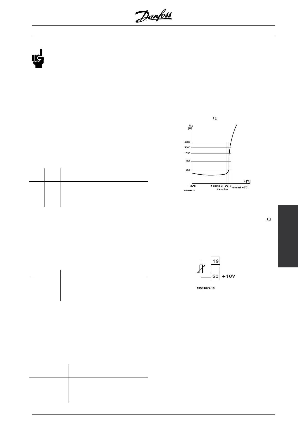
Thermistor is to be selected if a possibly integrated
thermistor in the motor is to be able to stop
the frequency converter if the motor overheats.
The cut-out value is 3 k
.
If a motor features a Klixon thermal switch ins tead, this
can a lso be connected to the input. If motors operate
in parallel, the thermistors/thermal switches can be
connected in series (total resistance lower than 3 k
).
Parameter 128 Motor thermal protection must be
programmed for Thermistor warning [1] or Thermistor
trip [2] and the the rmistor is to be connected betw een
a d igital input and terminal 50 (+ 10 V supply).
Precise stop, inverse is selected to obtain a high
degree of a ccuracy when a stop command is
repeated. A logic 0 means that th
e motor speed is
ramped down to stop via the selected ramp.
Precise start/stop is selected to obtain a high degree of
accuracy when a start and stop command is repeated.
Pulse reference is selected if the reference
signal applied is a pulse
train (frequency). 0 Hz
corresponds to parameter 204 Minimum reference,
Ref
MIN
. The frequency set in parameter 327 Pulse
reference/feedbac
k corresponds to parameter
205 Maximum reference Ref
MAX
.
Pulse feedback is selected if the feedback signal
used is a pulse train (frequency). In parameter
✭
= factory setting. () = display text [] = value for use in communication via serial communication port
MG.28.E9.02 - VLT is a registered Danfoss trademark
89
 Loading...


