MATRIX 210™ QUICK GUIDE
4
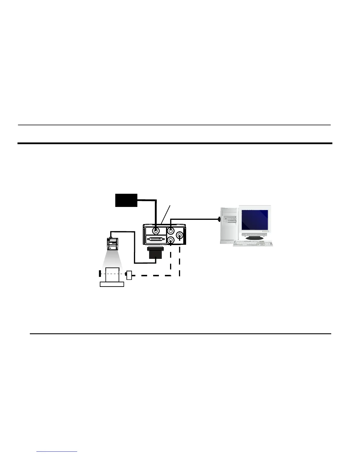
STEP 1 – CONNECT THE SYSTEM
25-Pin Models
To connect the system in a Stand Alone configuration, you need the hardware indicated in Figure 1. In this layout the data is
transmitted to the Host on the main serial interface. Data can also be transmitted on the RS232 auxiliary interface independently
from the main interface selection. When One Shot or Phase Mode Operating mode is used, the reader is activated by an External
Trigger (photoelectric sensor) when the object enters its reading zone.
Figure 1 – Matrix 210™ 25-Pin Model in a Stand Alone Layout
CBX100/CBX500 Pinout for Matrix 210™ 25-Pin Models
The table below gives the pinout of the CBX100/CBX500 terminal block connectors. Use this pinout when the Matrix 210™ reader
is connected by means of the CBX100/CBX500:
Matrix 210™
Host
PG 6000
P.S.*
* External Trigger or Presence Sensor
(for One Shot or Phase Mode)
CBX
Main Interface
I/O, AUX