Chapter 4 – Maintenance and Adjustments 31
4
4
4
.
.
.
4
4
4
A
A
A
d
d
d
j
j
j
u
u
u
s
s
s
t
t
t
a
a
a
b
b
b
l
l
l
e
e
e
M
M
M
e
e
e
d
d
d
i
i
i
a
a
a
S
S
S
e
e
e
n
n
n
s
s
s
o
o
o
r
r
r
The optional Adjustable Media Sensor (AMS) allows the printer to accept a wider variety of media
configurations. The table below defines general AMS positions for various media and Top of Form (TOF) types.
AMS Positioning
Media Type
Sensor Location TOF Sensing Method
Continuous
Center of the Media Continuous
Die-Cut
Center of the Label
Gap
Notched
Center of the Notch
Reflective
Center of the Mark Reflective
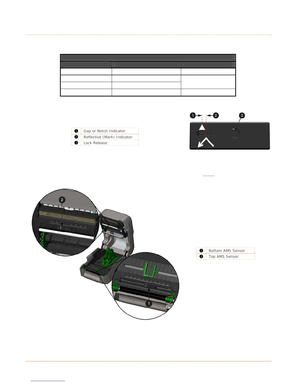
Position the AMS as follows:
1) On the Bottom AMS Sensor, identify the proper Indicator
for use with your media.
Gap or Notch Indicator
Reflective (Mark) Indicator
Lock Release
2) Depress the Lock Release and slide the Bottom AMS sensor so the Indicator is in line with the
center of the notch, gap, or reflective (mark) of the installed media.
3) Depress the Lock Release and slide the Top AMS Sensor over to the same setting as the Bottom
AMS Sensor, (this is not necessary if using reflective media).
312
Bottom AMS Sensor
Top AMS Sensor
4) Load media, see Section 2.3.