PRELIMINARY
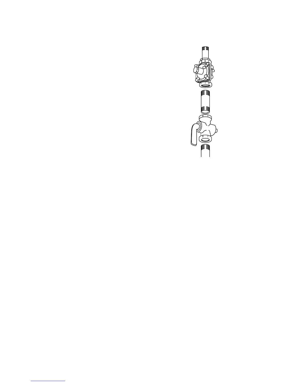
Regulator
Solid Piping
or Flexible
Connector
Shut-Off
Valve
Pipe Stub
Connection: 1/2″ N.P.T.
Minimum 5/8″ Dia. Metal Flex Line
1. CHECKING THE GAS SUPPLY
Measure the incoming gas pressure to the regu-
lator.
With the installation of this conversion kit, the
cooktop should operate on LP gas at 10″ of wa-
ter column pressure and on natural gas at 4″ of
water column pressure.
• The pressure regulator must be con-
nected in series with the manifold of the
cooktop and must remain in series with
the supply line.
• When checking the regulator, the inlet
pressure must be at least 1″ greater than
the regulator output setting.
– If the regulator is set for 10″ of water
column pressure, the inlet pressure
must be at least 11″.
For proper operation, the maximum inlet pres-
sure to the regulator must be no more than 14″
of water column pressure for LP gas and 9″
water column pressure for natural gas.
IMPORTANT:
Disconnect the cooktop and the individual
shut-off valve from the gas supply piping sys-
tem during any pressure testing of that system
at test pressures greater than 1/2 psig. Isolate
the cooktop from the gas supply piping system
by closing the individual manual shut-off valve
to the cooktop during any pressure testing of
the gas supply piping system at test pressures
equal to or less than 1/2 psig.