Delem
V0208, 2.41
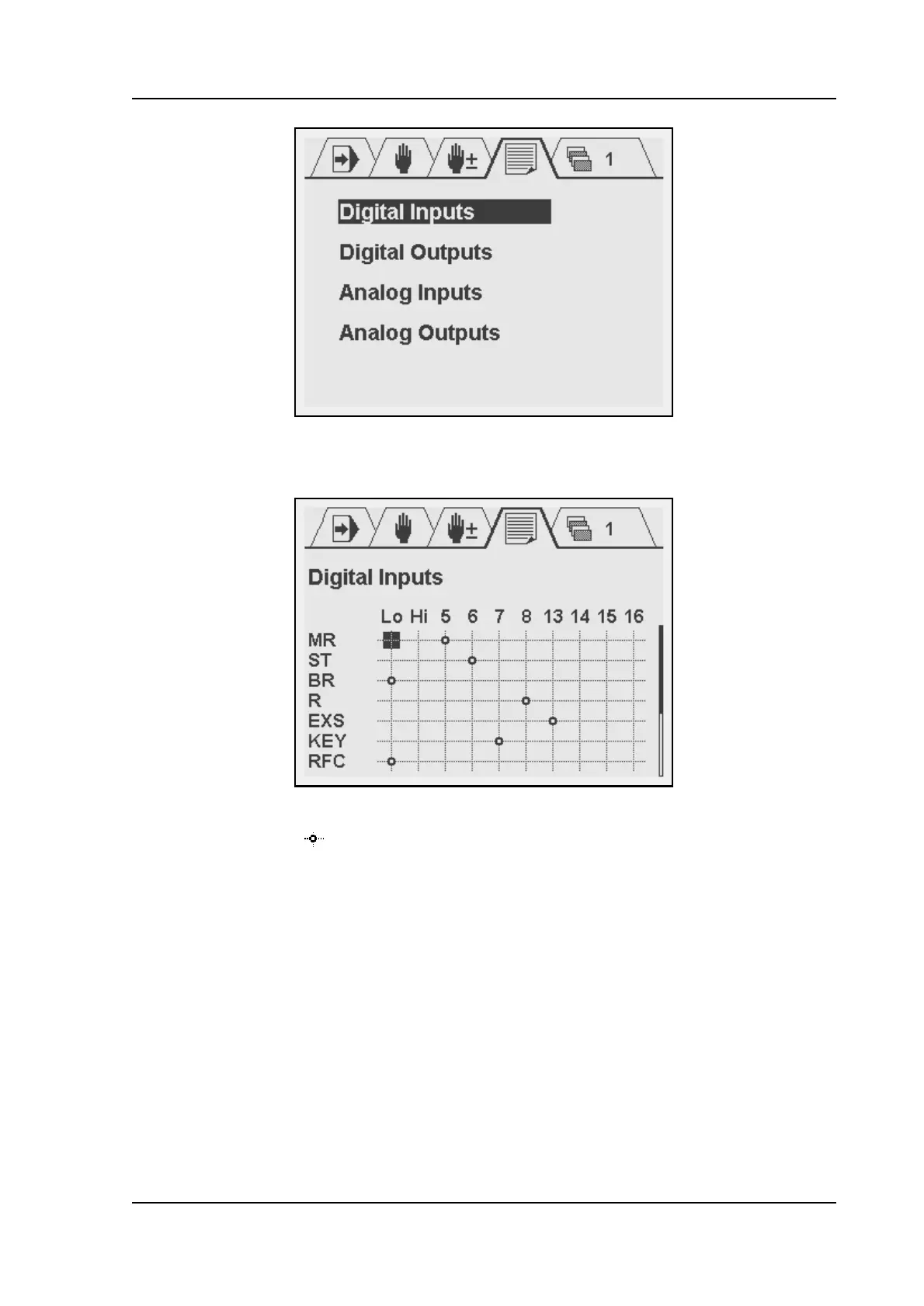
Each choice opens a sub-menu with an array of the logical signals and available connector
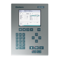
pins. The screen for digital inputs looks as follows:
In the top row, the available connector pins are shown. In the left column, the logical signals
are listed. The symbol indicates that there is a connection between the pin and the logical
signal. A signal is linked to an input pin as follows:
• move the cursor with the arrow keys and +/- keys to the necessary intersection;
•press ENTER.
To erase a connection, go to it with the cursor and press ENTER. The connection will
disappear.
The numbers 5-8 and 13-16 refer to the digital inputs of the DAC. ‘0’ is a logical FALSE. If a
signal is linked to this, it is always regarded as low (not active). ‘1’ is a logical TRUE. If a signal
is linked to this, it as always regarded as high (active).
For digital outputs the method works similar. In the case of outputs, several logical signals can
be mapped to the same output pin. They are processed as a logical OR: if one or more of
these signals become high, the output pin becomes high.