V0208, 2.40
3. I/O assignments
3.1. Inroduction
The control has several programmable features. These features can be enabled or disabled in
software. Depending on these featues, a number of logical signals can be mapped to the I/O
pins of the control.
This means the system programmer can enable the necessary signals and assign them to
output pins. The I/O settings should be adjusted by authorized personnel only.
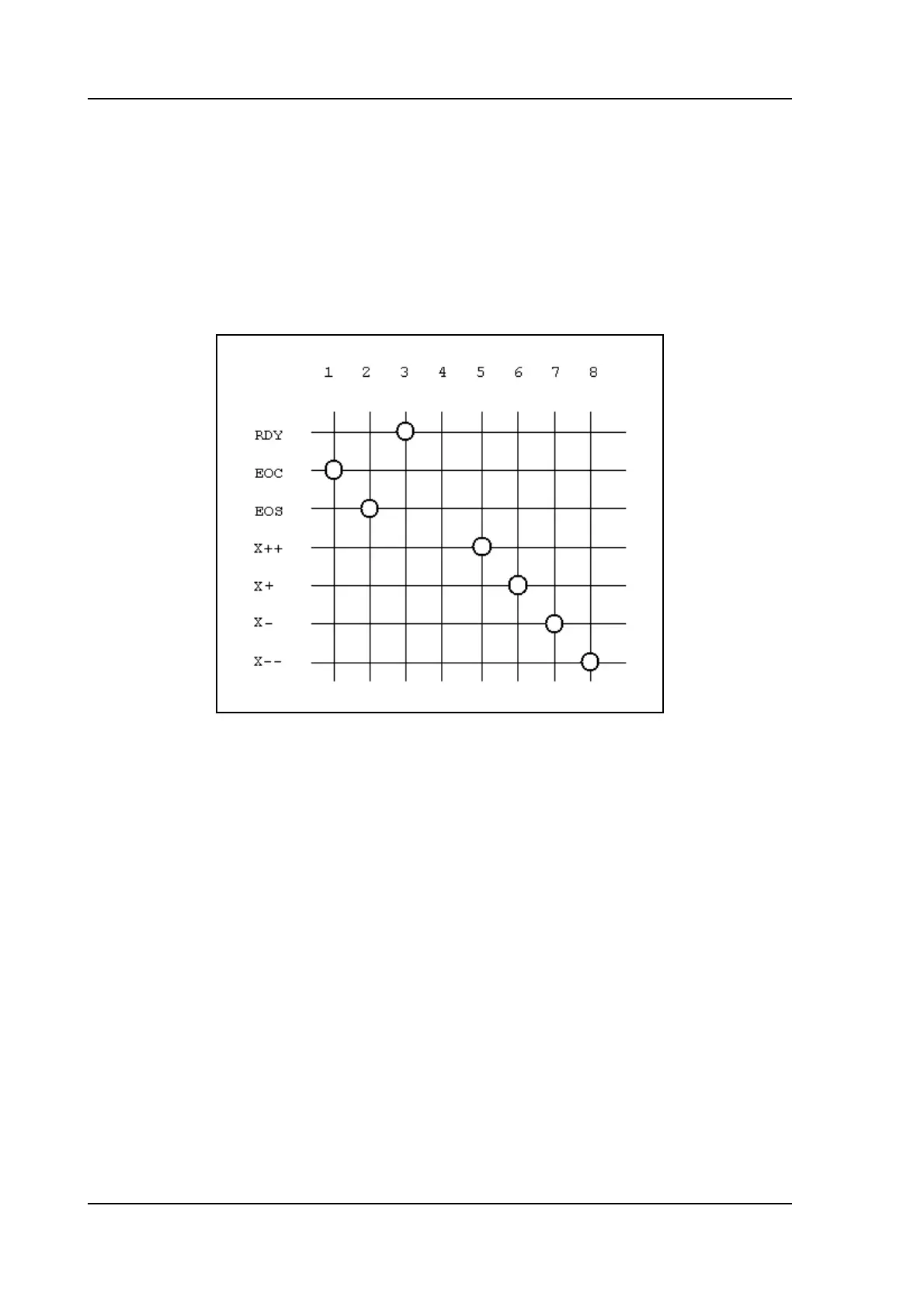
Example:
The example picture above shows an example of a possible mapping of output pins. In the
picture, pins 5 - 8 are allocated for the movement of a 2-speed AC drive, fast and slow in both
directions. If the system has a servo drive, those signals are not necessary. Then you could
delete these connections (the intersections) and use output 5 - 8 for other pusposes.
See also the schematics in part I of this manual for connection examples.
To enter the I/O allocation mode:
• enter the machine parameter menu as described in chapter 1;
• scroll to the menu ‘IO mapping’ and press ENTER.
The following screen appears: