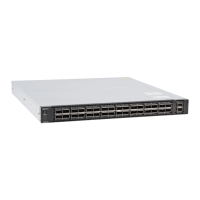
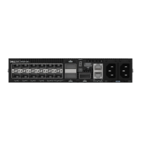
S5200F-ON Series switch installation
To install the S5200F-ON Series (S5232F-ON, S5248F-ON, and S5296F-ON) switch, complete the installation procedures in the order
presented in this chapter.
Always handle the switch and components with care. Avoid dropping the switch or its eld replaceable units (FRUs).
For the S5248F-ON and S5232F-ON switches, you can install the ReadyRails system. Due to the chassis weight, the S5296F-ON switch
does not support a two-post rack installation; you must install the S5296F-ON in a four-post rack. For the S5296F-ON switch installation
instructions, see S5296F-ON four-post rack assembly.
NOTE: ESD damage can occur if components are mishandled. Always wear an ESD-preventive wrist or heel ground strap when
handling the S5200F-ON Series switch and components. As with all electrical devices of this type, take all the necessary safety
precautions to prevent injury when installing this switch.
Topics:
• Unpack
• Rack or cabinet hardware installation
• ReadyRails installation
• Switch installation
• S5296F-ON four-post rack assembly
• Ground cable
• Optics installation
• Optics removal
• Switch start up
• After switch placement
• Switch replacement
Unpack
NOTE
: Before unpacking the switch, inspect the container and immediately report any evidence of damage.
When unpacking the switch, make sure that the following items are included:
NOTE
: For the S5296F-ON switch only: the USB extension cable is packaged separately. Do not throw it away.
• One S5200F-ON Series (S5232F-ON, S5248F-ON, or S5296F-ON) switch
• One RJ-45 to DB-9 female cable
• Two sets of rail kits; no tools required
• AC Ground lug kit
• DC ground lug kit—included in the accessories box
• Two PSUs
• Four fan units
• Two AC power cords; country or region specic
• One USB extension cable, male-to-female, package separately—S5296F-ON only
• S5200F-ON Series Set-up Guide
4
S5200F-ON Series switch installation 23
 Loading...