drives as evenly as possible across the buses. The rule of load or bus balancing is
applied to all DAEs.
Cabling the first optional DAE to create back-end bus 1
Connect the first optional expansion DAE to port 1 of the DPE to create back-end bus
1 (BE1) and designate this DAE as enclosure 0 of this bus. We refer to the address of
this enclosure as BE1 Enclosure 0 (1_0).
To prepare for this cabling task:
l
Locate the mini-SAS HD cables to be used to connect to the newly installed
expansion DAE. Typically these cables are two-meters long. You use longer cables,
typically five-meters or eight-meters, to connect enclosures located in different
racks. Cables are shipped without labels attached. The cables and ports are not
colored.
l
Locate the sheet of cable labels provided.
Orient the cable connectors as described in the procedure that follows, making sure
that you do NOT connect:
l
A DPE expansion port 0 to another DPE expansion port 0
l
Any A-side ports to B-side ports
Procedure
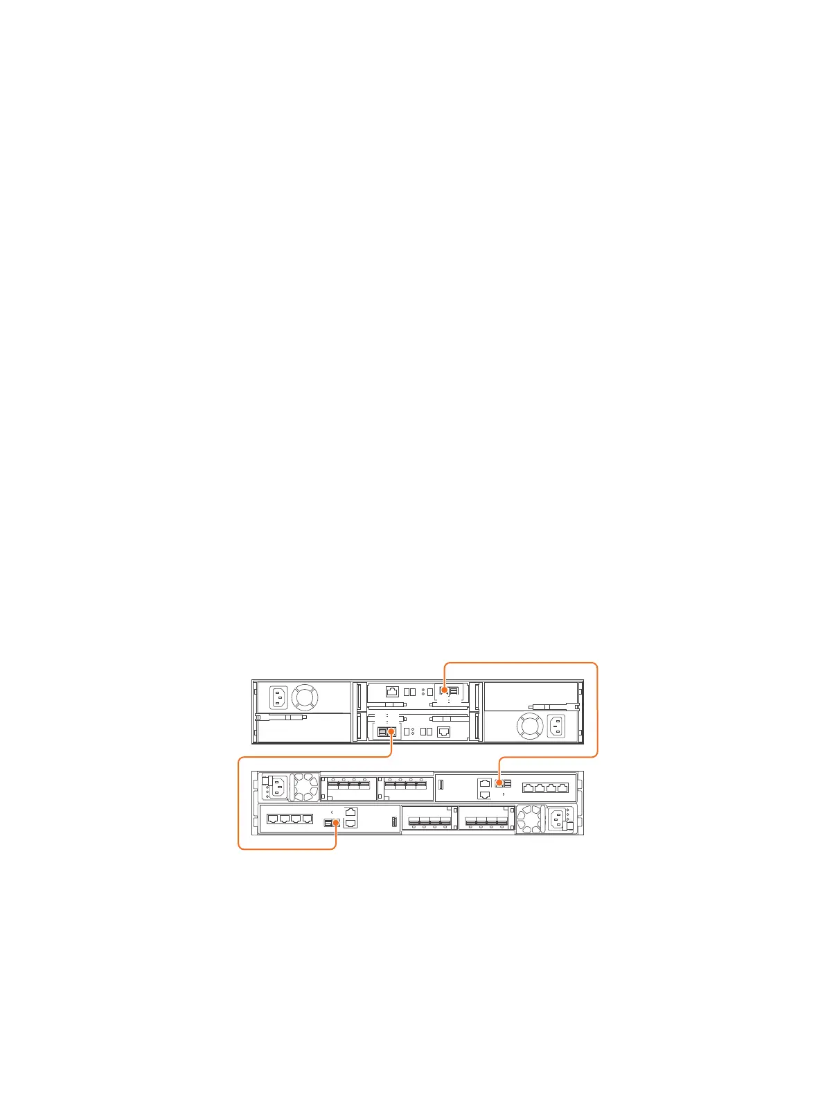
1. Label a pair of mini-SAS HD cables.
2. Connect port 1 on SP A in the bottom slot of the DPE to port A on the link
control card (LCC A) in the bottom of the DAE.
3. Connect port 1 on SP B in the top slot of the DPE to port A on the link control
card (LCC B) in the top of the DAE.
Figure 22
Cabling one DPE to one 25-drive DAE
Installation Procedures
36 Unity 480/F, Unity 680/F, Unity 880/F Installation and Service Guide
 Loading...
