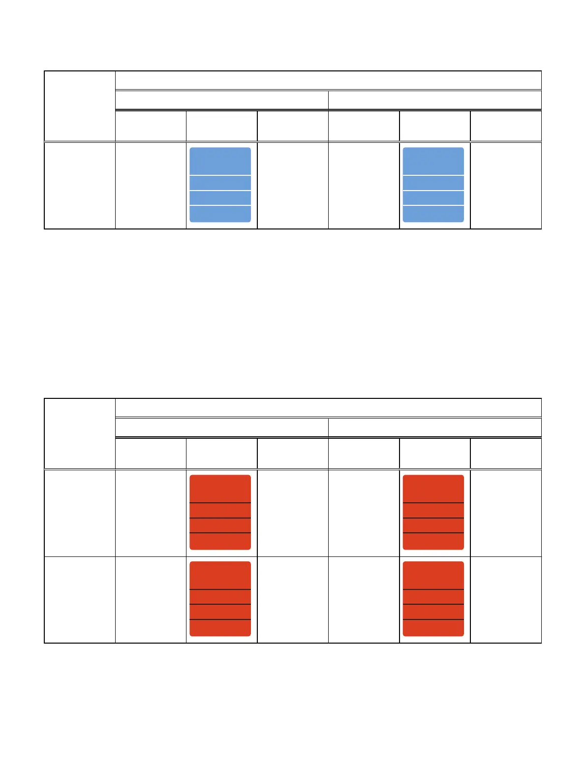
Back-end bus
and enclosure
number
Cable label
Expansion port cable labeling details Primary port cable labeling details
Label part
number
Label Port Label part
number
Label Port
BE1 Enclosure 0
- B-side
046-003-750
SP B SAS 1
SP B SAS 1
SP B SAS 1
SP B SAS 1
046-003-750_xx
SP B SAS 1 046-021-013
LCC B PORT A
046-021-013_xx
LCC B PORT A
LCC B PORT A
LCC B PORT A
LCC B Port A
b. Connect the ports as follows:
n
Connect BE port 1 on SP A (the bottom storage processor of the DPE) to
port A of link control card A (LCC A) on the right side of the DAE.
n
Connect BE port 1 on SP B (the top storage processor of the DPE) to port
A of link control card B (LCC B) on the left side of the DAE.
l
Connect to back-end bus 0: To connect the second optional expansion DAE to the
DPE expansion port 0 to extend back-end bus 0 (BE0) and designate this DAE as
Enclosure Address 1 of this bus. We refer to the address of this enclosure as BE0
EA1 (0_1):
a. Label a pair of mini-SAS HD cables using the orange labels shown here.
Back-end bus
and enclosure
number
Cable label
Expansion port cable labeling details Primary port cable labeling details
Label part
number
Label Port Label part
number
Label Port
BE0 Enclosure 1
- A-side
046-001-561
SP A SAS 0
SP A SAS 0
SP A SAS 0
SP A SAS 0
046-001-561_xx
SP A SAS 0 046-021-010
046-021-010_xx
LCC A PORT A
LCC A PORT A
LCC A PORT A
LCC A PORT A
LCC A Port A
BE0 Enclosure 1
- B-side
046-003-489
SP B SAS 0
SP B SAS 0
SP B SAS 0
SP B SAS 0
046-003-489_xx
SP B SAS 0 046-021-011
046-021-011_xx
LCC B PORT A
LCC B PORT A
LCC B PORT A
LCC B PORT A
LCC B Port A
b. Connect the ports as follows:
n
Connect BE port 0 on SP A (the bottom storage processor of the DPE) to
port A of link control card A (LCC A) on the right side of the DAE.
n
Connect port 0 on SP B (the top storage processor of the DPE) to port A of
link control card B (LCC B) on the left side of the DAE .
Field Upgrade Procedure
32 Unity All Flash and Unity Hybrid Field Upgrade Procedure

 Loading...


