14
Disassembly and reassembly
Disassembly and reassembly
CAUTION: The information in this section is intended for authorized service technicians in the EMEA region. Dell prohibits
users from disassembling the monitor, and any damage caused by unauthorized servicing will not be covered under the
warranty.
Recommended tools
The procedures in this document may require the following tools:
• Screwdriver (Phillips-head, Hexagonal head)
• Plastic scribe
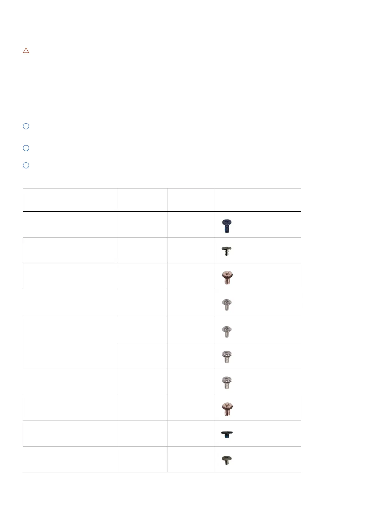
Screw list
NOTE: When removing screws from a component, it is recommended to note the screw type, the quantity of screws, and then
place them in a screw storage box. This is to ensure that the correct number of screws and correct screw type is restored when
the component is replaced.
NOTE: Some computers have magnetic surfaces. Ensure that the screws are not left attached to such surfaces when replacing a
component.
NOTE: Screw color may vary with the configuration ordered.
Table 6. Screw list.
Component Screw types Quantity Screw images
Back cover M4x10
4
Speaker M3x6
6
Metal shield M3x4
3
System board D3x6 4
Power board
D3x6 4
M4x6 1
Converter board D3x6 4
Middle frame M3x4 16
Front trim M2x2.0 6
Keypad board Q2x2.5 3