1-16 Dell PowerEdge 6100/200 System Service Manual
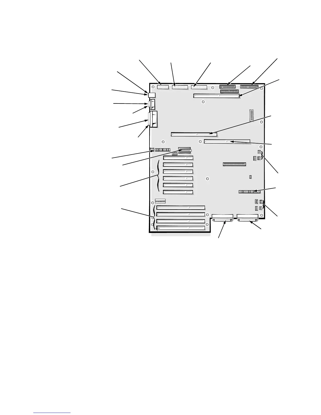
System Board Layout
The subsections that follow provide service-related information about the sys-
tem board components.
Figure 1-14. System Board Components
Connectors not supported/not used
•
IDE
•
J8G1
•
HD LED 1
•
J5E1
•
J4G1
•
I2C
•
HD LED 2
•
J2A3
•
C5B1
mouse connector
(MOUSE)
Ultra/Wide SCSI host
adapter connector (SCSI B)
server-
management
module
connector
(J3G1)
fan connectors
(FAN1 and FAN2)
front of
system board
control panel
connector
(FRONT PANEL)
memory module
connector
(MEMORY
MODULE)
secondary micro-
processor module
connector
(PROCESSOR
MODULE #2)
fan connectors
(FAN3 and FAN4)
Ultra/Wide SCSI host
adapter connector (SCSI A
primary micro-
processor
module connector
(PROCESSOR
MODULE #1)
power connector (PS3)
power connector
(PS1 or PS2)
power connector
(PS1 or PS2)
interface connector
(FLOPPY)
 Loading...


