I/O Ports and Connectors B-3
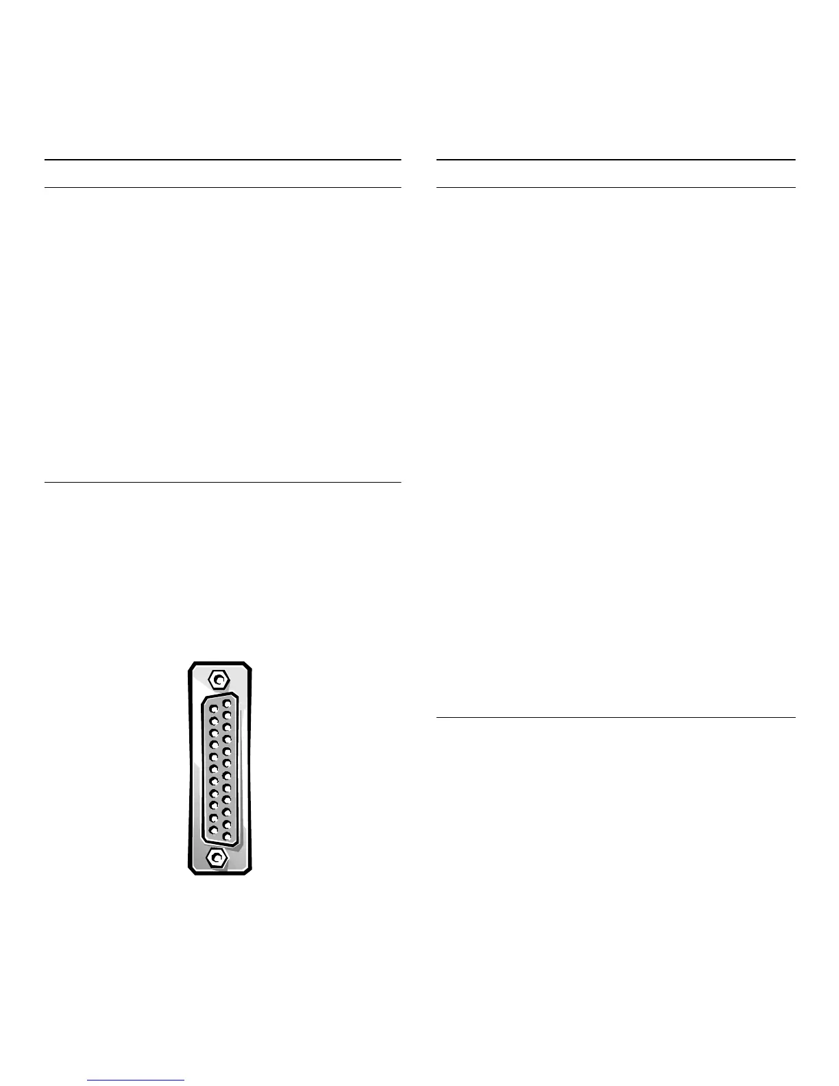
Parallel Port Connector
If
ou reconfi
ure
our hardware,
ou ma
need
in
number and si
nal information for the
arallel
ort con-
nector. Fi
ure B-3 illustrates the
in numbers for the
arallel
ort connector, and Table B-2 lists and defines
the
in assi
nments and interface si
nals for the
arallel
ort connector.
Figure B-3. Pin Numbers for the Parallel Port
Connector
K
eyboard and Mouse Connectors
The s
stem uses a Personal S
stem/2 (PS/2)-st
le ke
-
board and su
orts a PS/2-com
atible mouse. Cables
from both devices attach to 6-
in, miniature
Deutsche
Industrie Norm
(DIN) connectors on the back
anel of
our com
uter. The ke
board connector is on the left; the
mouse connector is on the ri
ht.
Table B-1. Pin Assignments for the Serial Port
Connectors
Pin Signal I/O Definition
1 DCD I Data carrier detect
2 RXD I Receive data
3 TXD O Transmit data
4 DTR O Data terminal read
5GND N/A Si
nal
round
6 DSR I Data set read
7RTS O Re
uest to send
8 CTS I Clear to send
9RIA I Rin
indicator
Shell N/A N/A Chassis
round
1 — 13
14 — 25
Table B-2. Pin Assignments for the Parallel
Port Connector
Pin Signal I/O Definition
1 Strobe # I/O Strobe
2 Data bit 0 I/O Printer data bit 0
3 Data bit 1 I/O Printer data bit 1
4 Data bit 2 I/O Printer data bit 2
5 Data bit 3 I/O Printer data bit 3
6 Data bit 4 I/O Printer data bit 4
7 Data bit 5 I/O Printer data bit 5
8 Data bit 6 I/O Printer data bit 6
9 Data bit 7 I/O Printer data bit 7
10 ACK # I Acknowled
e
11 Bus
IBus
12 PE I Pa
er end
13 SLCT I Select
14 AUFDXT# O Automatic feed
15 Error # I Error
16 INIT O Initialize
rinter
17 SLCTIN # O Select in
18-25 GND N/A Si
nal
round