EasyManuals Logo

Dell Alienware Aurora R16 User Manual

Dell Alienware Aurora R16
114 pages
To Next Page IconTo Next Page
To Previous Page IconTo Previous Page
Page #94 background imageLoading...
Page #94 background image
About this task
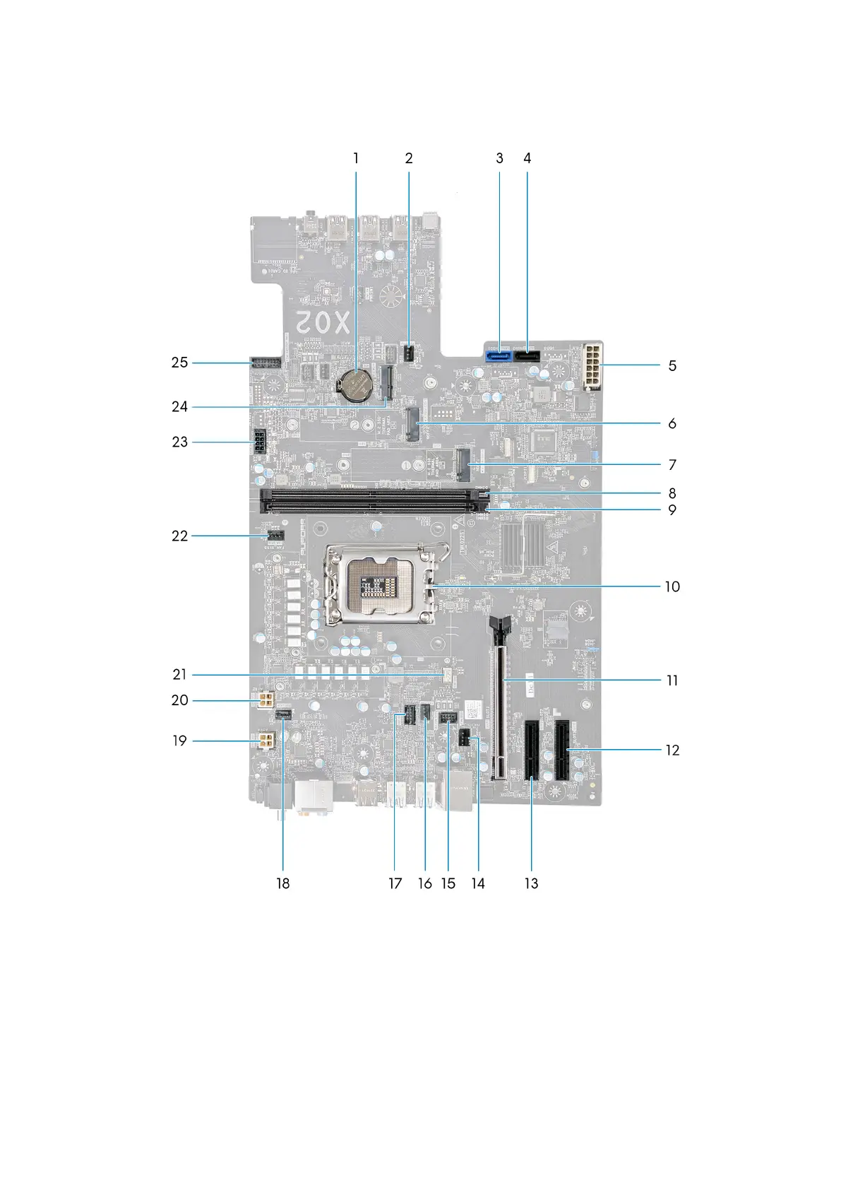
The following image indicates the connectors on your system board.
1. Coin-cell battery 2. Lower front-chassis fan connector (FAN_SYS2)
3. SATA 6 Gbps drive connector (HDD1) 4. SATA 6 Gbps drive connector (HDD2)
5. Power-supply connector (ATX1) 6. Solid-state drive slot (M.2 PCIe SSD-2)
7. Solid-state drive slot (M.2 PCIe SSD-1) 8. Memory-module slot, DIMM1
9. Memory-module slot, DIMM2 10. CPU socket
11. PCI-Express x16 mechanical/x16 electrical slot (SLOT1) 12. PCI-Express x4 slot (SLOT3)
13. PCI-Express x4 slot (SLOT2) 14. Rear-chassis fan connector (FAN SYS1)
15. Rear-chassis fan LED connector (LED FAN SYS1) 16. Liquid cooling pump fan connector (FAN PUMP)
17. Liquid-cooling pump LED connector 18. Top-chassis fan connector one (FAN_SYS4)
94

Table of Contents

Questions and Answers:

Question and Answer IconNeed help?

Do you have a question about the Dell Alienware Aurora R16 and is the answer not in the manual?

Dell Alienware Aurora R16 Specifications

General IconGeneral
ChipsetIntel Z790
GPUUp to NVIDIA GeForce RTX 4090
GraphicsNVIDIA GeForce RTX 4090
MemoryUp to 64GB DDR5
StorageUp to 4TB NVMe SSD + 2TB HDD
Operating SystemWindows 11 Home, 64-bit
Front Ports2x USB 3.2 Gen 1 Type-A, 1x USB 3.2 Gen 2 Type-C, 1x Headphone/Microphone combo jack
Rear Ports1x RJ45 Ethernet port
WirelessKiller Wi-Fi 6E AX1675 (2x2), Bluetooth 5.2

Related product manuals