72 Display Assembly
10
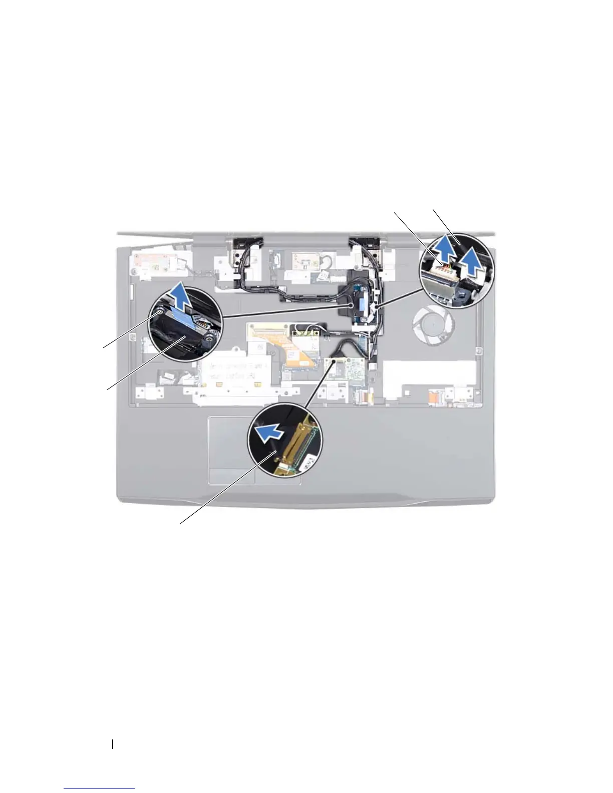
Disconnect the camera cable and infrared cable from the respective system
board connectors.
11
Note the routing of the display cable, camera cable, infrared cable,
wirelessHD card cable, Mini-Card antenna cables and remove the cables
from the routing guides on the palm rest assembly.
12
Remove the six screws that secure the display assembly to the computer
base.
13
Lift the display assembly off the computer.
1 wirelessHD card cable 2 display cable
3 captive screws (2) 4 camera cable
5 infrared cable
 Loading...