Removing and Replacing Parts 4-3
5HSHDW VWHS IRU WKH RWKHU FRYHU UHOHDVH ODWFK
6OLGH WKH FRYHU DSSUR[LPDWHO\ RQH LQFK WRZDUG WKH EDFN RI WKH
FRPSXWHU 7 KHQ OLIW WKH FRYHU RII W KH FRPSXWHU
%H]HO
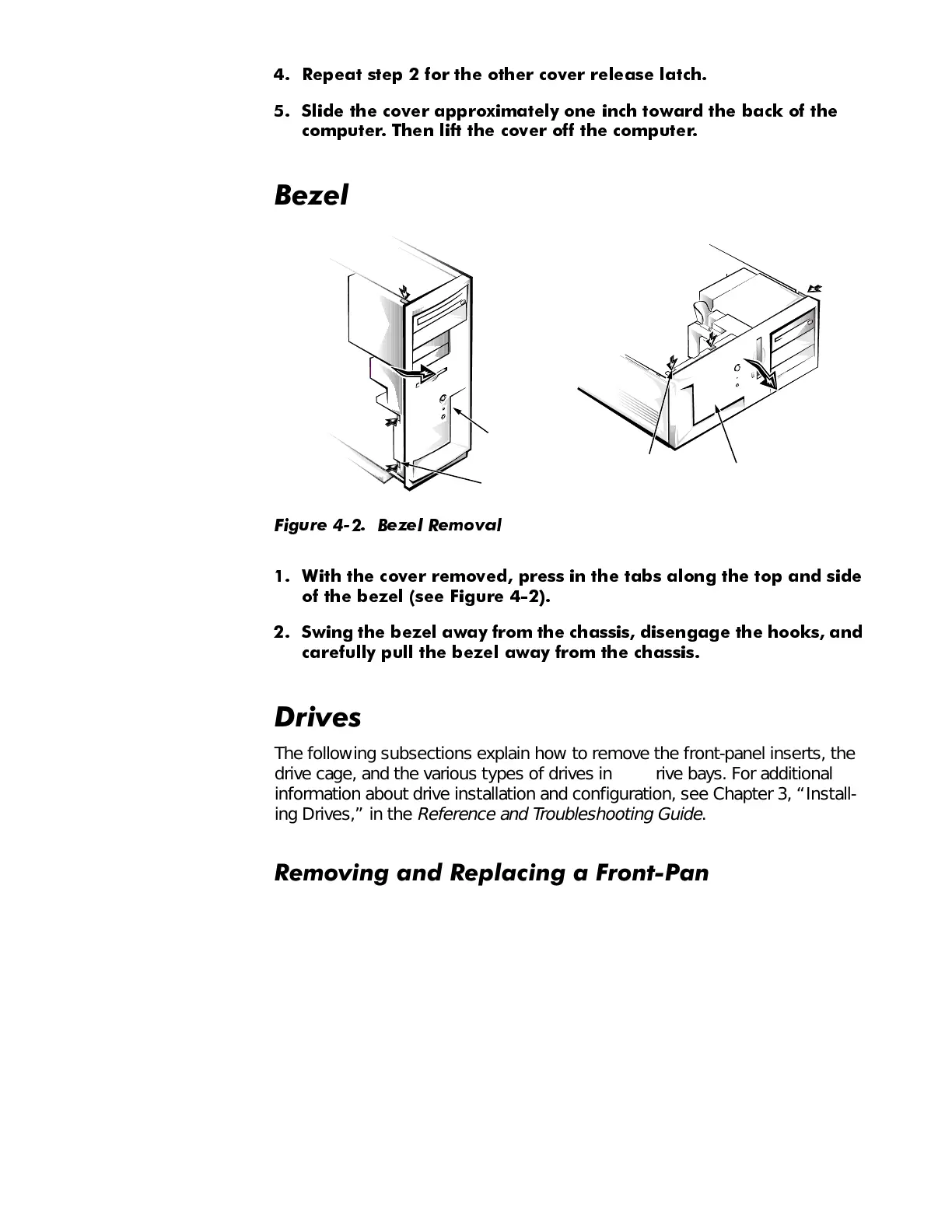
)LJXUH %H]HO 5HPRYDO
:LWK WKH FRYHU UHPRYHG SUHVV L Q WKH WDEV DORQJ WKH WRS DQG VLGH
RI WKH EH]HO
VHH )LJXUH
6ZLQJ WKH EH]HO DZD\ IURP WK H FKDVVLV GLVHQJDJH WKH KRRNV DQG
FDUHIXOO\ SXOO WKH EH]HO DZD\ IURP WKH FKDVVLV
'ULYHV
The following subsections explain how to remove the front-panel inserts, the
drive cage, and the various types of drives in the drive bays. For additional
information about drive installation and configuration, see Chapter 3, “Install-
ing Drives,” in the
Reference and Troubleshooting Guide
.
5HPRYLQJDQG5HSODFLQJD)URQW3DQHO,QVHUW
Empty drive bays in the drive cage are covered by a front-panel insert. The
inserts for the 3.5-inch drives are mounted to the inside of the bezel. The insert
for the lower 5.25-inch bay is mounted to the drive cage, and instructions for
its removal are provided later in this chapter in the procedure for removing the
5.25-inch drives.
tabs (3)
bezel
bezel
tabs (3)
 Loading...