EasyManuals Logo

Dell EMC PowerEdge C6420 Installation And Service Manual

Dell EMC PowerEdge C6420
92 pages
To Next Page IconTo Next Page
To Previous Page IconTo Previous Page
Page #38 background imageLoading...
Page #38 background image
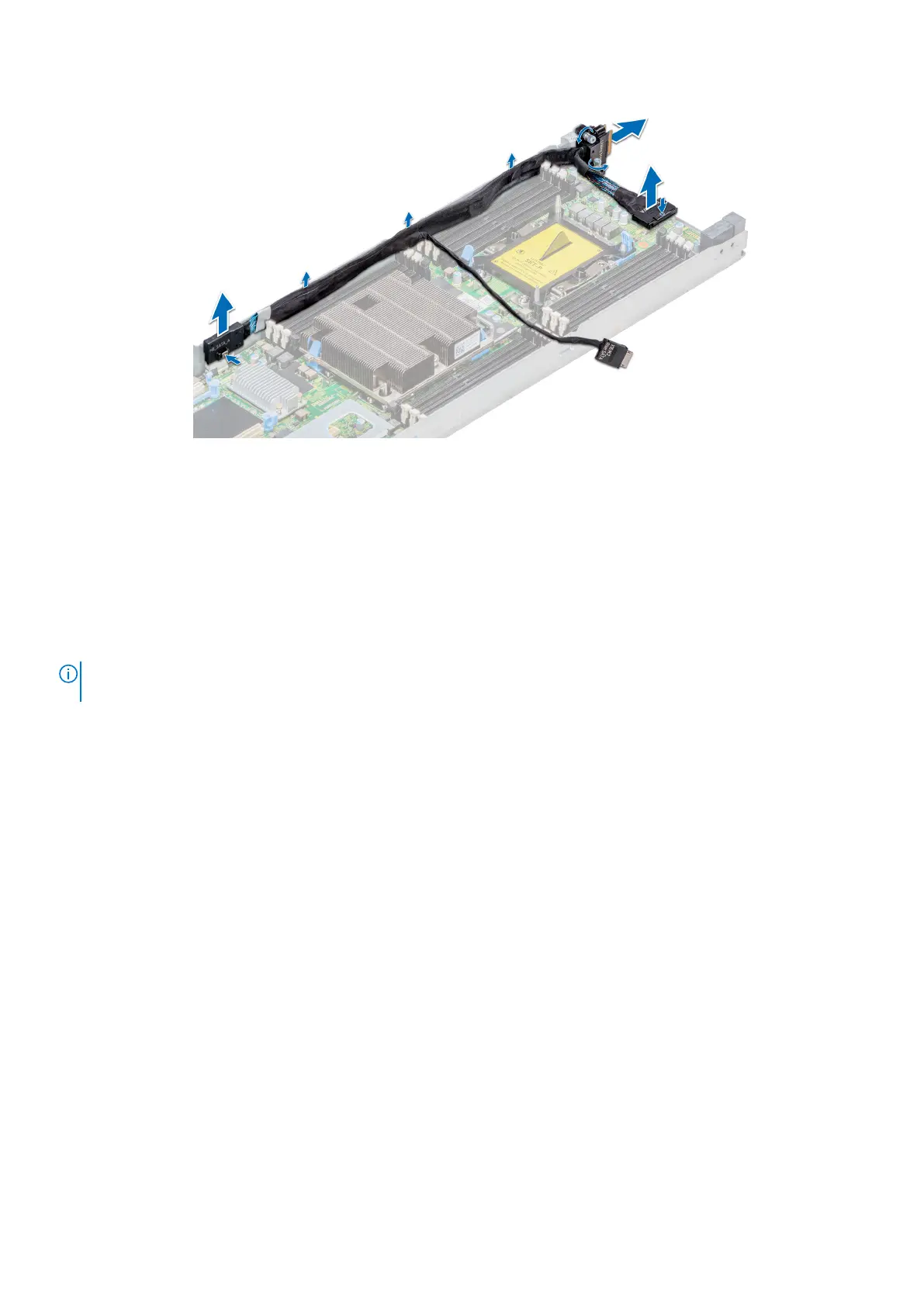
Figure 27. Removing the linking board and SATA cable
Next steps
1. Install the linking board and PCIe cables.
Installing the linking board and PCIe cables
Prerequisites
NOTE:
Observe the routing of the cable as you remove it from the sled. Route the cable properly when you replace it to
prevent the cable from being pinched or crimped.
1. Follow the safety guidelines listed in Safety instructions.
Steps
1. Insert the PCIe_A connector into the connector on the system board, press the connector until it locks into place.
2. Insert and press the PCIe_B connector into the connector on the system board, press the connector until it locks into place.
3. If disconnected, reconnect the SATA cable to the x16 M.2 riser.
4. Using the Phillips #1 screwdriver, tighten the captive screws on the linking board to secure the board to the sled.
38
Installing and removing enclosure components

Table of Contents

Other manuals for Dell EMC PowerEdge C6420

Questions and Answers:

Question and Answer IconNeed help?

Do you have a question about the Dell EMC PowerEdge C6420 and is the answer not in the manual?

Dell EMC PowerEdge C6420 Specifications

General IconGeneral
ProcessorIntel Xeon Scalable processors
ManagementiDRAC9
Max Processors2 per node
MemoryDDR4
StorageUp to 6 x 2.5" drives
Drive Bays24 x 2.5" or 12 x 3.5"
Network2 x 10GbE ports per sled
Power SupplyDual, 2000W
Operating System SupportWindows Server, Red Hat Enterprise Linux, SUSE Linux Enterprise Server, VMware ESXi
Maximum RAMUp to 3TB per node
Max MemoryUp to 3TB per node

Related product manuals