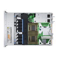
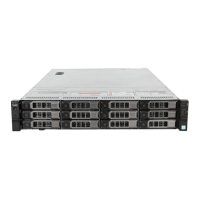
Table 43. Supported hard drives supported options for PowerEdge R730xd systems
System Model Supported hard drives options
PowerEdge R730
2.5 inch (x24) SAS/SATA backplane or
2.5-inch (x24) SAS/SATA backplane, which supports flexible
zoning using dual PERC H730p controllers with 12 and 12
drives split mode, 4 and 20 drives split mode, 8 and 16 drives
split mode, 16 and 8 drives split mode and 20 and 4 drives split
mode, or
2.5 inch (x24) SAS/SATA, which includes 2.5 inch (x4) Dell
PowerEdge Express Flash (PCIe SSD) backplane and 2.5 inch
(x2) SAS/SATA backplane (back), or
2.5 inch (x24) SAS/SATA, which includes 2.5 inch (x4) Dell
PowerEdge Express Flash (PCIe SSD) backplane, or
3.5 inch (x12) SAS/SATA backplane, or
3.5 inch (x12) SAS/SATA backplane, 3.5 inch (x4) SAS/SATA
backplane on the hard drive tray and 2.5 inch (x2) SAS/SATA
backplane (back) or
3.5 inch (x12) SAS/SATA backplane, and 2.5 inch (x2) SAS/
SATA backplane (back), or
1.8 inch (x18) uSATA SSD backplane, 3.5 inch (x8) SAS/SATA
backplane and 2.5 inch (x2) SAS/SATA backplane (back)
Removing the hard drive backplane
Prerequisites
CAUTION: Many repairs may only be done by a certified service technician. You should only perform
troubleshooting and simple repairs as authorized in your product documentation, or as directed by the online or
telephone service and support team. Damage due to servicing that is not authorized by Dell is not covered by
your warranty. Read and follow the safety instructions that are shipped with your product.
CAUTION: To prevent damage to the drives and backplane, you must remove the hard drives from the system
before removing the backplane.
CAUTION: You must note the number of each hard drive and temporarily label them before removal so that you
can replace them in the same locations.
1. Follow the safety guidelines listed in the Safety instructions section.
2. Follow the procedure listed in the Before working inside your system section.
3. Remove the cooling shroud.
4. Remove the cooling fan assembly.
5. Remove all hard drives.
Steps
1. Disconnect the SAS/SATA data, signal, and power cable(s) from the backplane.
2. Press the release tabs and lift the backplane upward and slide it toward the back of the chassis.
NOTE: To prevent damage to the control panel flex cable, unlatch the blocking tab on the connector before removing
the flex cable. Do not bend the flex cable at the connector. To unlatch the blocking tab for the x12 backplane, pull the
locking tab up. For the x18 and x2 backplanes, rotate the locking tab 90 degrees clockwise.
Installing and removing system components 171
 Loading...

