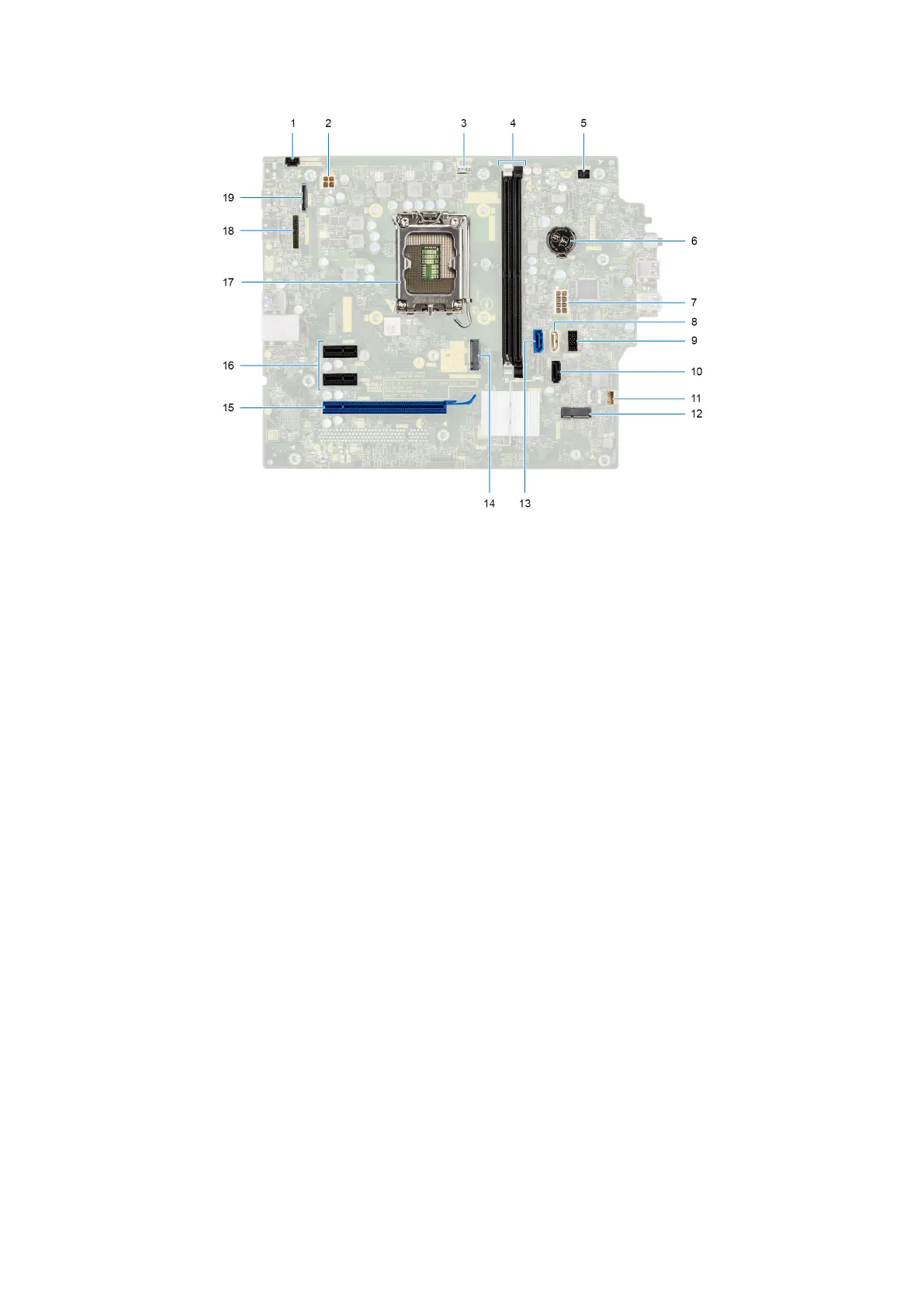
Figure 82. System board connectors
1. Intrusion-switch cable connector (INTRUSION)
2. Power-supply unit cable connector (ATX CPU)
3. Processor fan and heat-sink assembly cable connector (FAN CPU)
4. Memory module connectors (DIMM1 and DIMM2)
5. Power-button cable connector (PWR SW)
6. Coin-cell battery connector (RTC)
7. Power-supply unit cable connector (ATX SYS)
8. Slim optical-drive data cable connector (SATA3)
9. SATA power cable connector (SATA PWR)
10. Hard-drive data cable connector (SATA1)
11. Internal-speaker cable connector (INSKR1)
12. Wireless card connector (M.2 WLAN)
13. Hard-drive data cable connector (SATA0)
14. M.2 2230/2280 solid-state drive connector (M.2 PCIe SSD-0)
15. PCIe x16 card connector (SLOT3)
16. PCIe x1 card connectors (SLOT1 and SLOT2)
17. Processor socket (CPU)
18. Optional serial port connector (KB MS SERIAL)
19. Optional video port connector (VIDEO)
The following images indicate the location of the system board and provide a visual representation of the removal procedure.
Removing and installing Field Replaceable Units (FRUs)
107