Next steps
1 Reconnect all the disconnected cables.
2 Install the power supply units.
3 Follow the procedure listed in After working inside your system.
Related links
Installing a power supply unit
Chassis management board
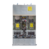
Figure 40. Chassis management board
1
fan cage 1 connector for fans 1 and 2 2 left midplane signal cable
3 chassis management board signal cable to backplane 4 chassis management board power connector from PIB
5 chassis management board signal cable to PIB 6 FPGA connector
7 MCU connector 8 COM connector
9 rmware jumpers 10 right midplane signal cable
11 fan cage 2 connector for fans 3 and 4
Removing the chassis management board
Prerequisites
1 Follow the safety guidelines listed in Safety instructions.
2 Follow the procedure listed in Before working inside your system.
3 Remove the power supply units.
4 Remove the power interposer board.
5 Disconnect all the cables that are connected to the chassis management board.
Dell PowerEdge C6400 Installation and Service Manual
Installing and removing enclosure components
57