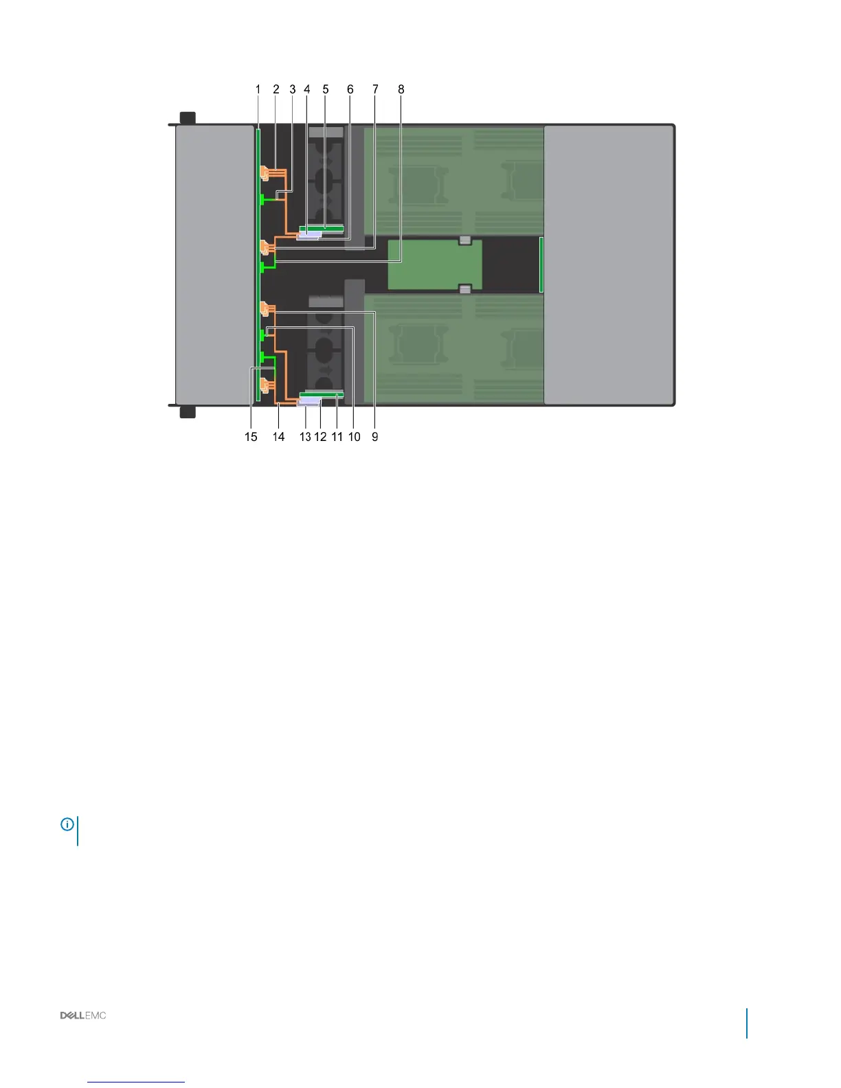
Figure 67. Cabling the 12 x 3.5 inch backplane
1
backplane 2 SATA cable for sled 1
3 signal cable sled 1 4 linking board connector for sled 1
5 left linking board 6 linking board connector for sled 2
7 SATA cable for sled 2 8 signal cable sled 2
9 SATA cable for sled 3 10 signal cable sled 3
11 right linking board 12 linking board connector for sled 3
13 linking board connector for sled 4 14 SATA cable for sled 4
15 signal cable sled 4
Control panel
Removing the control panel
Prerequisites
NOTE
: Observe the routing of the cables on the enclosure as you remove them. You must route these cables properly when you
replace them to prevent the cables from being pinched or crimped.
1 Follow the safety guidelines listed in Safety instructions.
2 Follow the procedure listed in Before working inside your system.
3 Remove all the drives.
4 Disconnect all the backplane cables from the linking board and chassis management board.
5 Remove the drive cage from the enclosure.
6 Disconnect control panel cables from the midplane.
Dell PowerEdge C6400 Installation and Service Manual
Installing and removing enclosure components
81