Do you have a question about the Dell PowerEdge C6400 and is the answer not in the manual?
Details the system's supported drive and sled configurations.
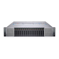
Illustrates the front of the enclosure with drive bays and control panels.
Details indicators and buttons on the left and right control panels.
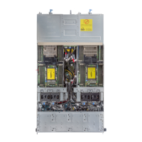
Shows the rear of the enclosure with sleds and power supply units.
Illustrates how sleds are mapped to drive bays for 2.5-inch and 3.5-inch configurations.
Explains system indicators for operation and error status, including drive status.
Details status lights for Network Interface Cards (NICs) and Power Supply Units (PSUs).
Guides on finding the system's Service Tag and Express Service Code.
Information on installing, securing, and setting up the system.
Resources for iDRAC, OpenManage, and system management software.
Guidance on downloading and updating system firmware and drivers.
Resources for event/error messages, server troubleshooting, and RAID controllers.
Provides physical dimensions (height, width, depth) of the enclosure.
Lists the maximum weight of the enclosure with different drive configurations.
Details wattage, class, heat dissipation, frequency, voltage, and input current for PSUs.
Information on supported SAS/SATA drives and SSDs for the sled.
Defines operating and storage temperature ranges and gradients.
Specifies operating and storage relative humidity limits.
Details maximum vibration and shock tolerances for system operation and storage.
Specifies maximum operating and storage altitudes for the system.
Explains how temperature limits are adjusted based on altitude.
Defines limits for particulate and gaseous contaminants in the operating environment.
Lists standard operating temperature ranges for various configurations.
Table detailing operating temperatures for various CPU/HDD configurations.
Table detailing operating temperatures for fabric dual processor configurations.
Table detailing operating temperatures for non-fabric single processor configurations.
Table detailing operating temperatures for fabric single processor configurations.
Details conditions for operation outside standard temperature ranges, including de-rating.
Lists components and configurations not supported in Fresh Air mode.
Crucial safety warnings and precautions before performing component installation/removal.
Prerequisites and steps to prepare the system before internal work.
Prerequisites and steps for completing work after internal component changes.
Lists necessary tools for component installation and removal.
Diagram identifying key internal components of the C6400 enclosure.
Step-by-step guide for safely removing a server sled from the enclosure.
Step-by-step guide for safely installing a server sled into the enclosure.
Procedure for removing a hard drive from its carrier within the enclosure.
Procedure for installing a hard drive into its carrier within the enclosure.
Instructions for removing empty drive bay fillers.
Instructions for installing empty drive bay fillers.
Detailed steps to detach a hard drive from its carrier.
Detailed steps to attach a hard drive to its carrier.
Procedure for safely removing a PSU from the enclosure.
Procedure for safely installing a PSU into the enclosure.
Steps to remove the main chassis cover for access to internal components.
Steps to reattach the main chassis cover after component service.
Procedure for removing the cover protecting the backplane, not for 3.5-inch configurations.
Procedure for reinstalling the backplane cover.
Steps to safely remove a single cooling fan module.
Steps to safely install a single cooling fan module.
Procedure to remove the entire fan cage assembly.
Procedure to install the entire fan cage assembly.
Diagram and description of the power interposer board.
Steps to safely remove the PIB, including precautions for discharging.
Steps to safely install the PIB, including connecting power cables.
Procedure to remove the chassis management board and its cables.
Procedure to install the chassis management board.
Steps to remove the linking board connecting sleds to the backplane.
Steps to install the linking board connecting sleds to the backplane.
Procedure to remove the right midplane assembly.
Procedure to install the right midplane assembly.
Procedure to remove the left midplane assembly.
Procedure to install the left midplane assembly.
Diagram showing how midplane power cables are routed.
Procedure to remove the 2.5-inch drive cage assembly.
Procedure to install the 2.5-inch drive cage assembly.
Procedure to remove the 3.5-inch drive cage assembly.
Procedure to install the 3.5-inch drive cage assembly.
Diagrams and labels for 2.5-inch backplanes and expander boards.
Procedure to remove the backplane from the drive cage.
Procedure to install the backplane onto the drive cage.
Procedure to remove the backplane expander board.
Procedure to install the backplane expander board.
Diagram showing NVMe backplane cabling for sleds.
Diagram showing backplane cabling with expander board.
Diagram showing 12 x 3.5-inch backplane cabling for sleds.
Procedure to remove the left and right control panel assemblies.
Procedure to install the left and right control panel assemblies.
Procedure to remove the thermal sensor board assembly.
Procedure to install the thermal sensor board assembly.
Details on Dell's automated support service for issue detection and case creation.
Instructions on how to contact Dell support via website or phone.
How to provide feedback on the documentation.
Guide to using Quick Resource Locator (QRL) for system details.
| Processor | Intel Xeon |
|---|---|
| Memory | DDR |
| Network Interface | 1GbE, 10GbE |
| Number of Nodes | 4 |
| Processor per Node | 2 |
| Operating System Support | Linux, VMware, Windows Server |