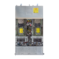
Midplane power cable routing
Figure 52. Midplane power cable routing from power interposer board
1
left midplane 2 +12 V power cable for left midplane
3 GND cable for left midplane 4 power interposer board
5 +12 V power cable for right midplane 6 GND cable for right midplane
7 right midplane
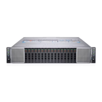
Drive cage
The drive cage contains the drives, the backplane, and the expander board.
The drive cage supports the following drive congurations:
• up to 24 x 2.5 inch SAS or SATA drives
• up to 8 x 2.5 inch NVMe drives, with 16 x 2.5 inch SAS or SATA drives
• up to 12 x 3.5 inch SAS or SATA drives
• diskless no backplane
Removing the 2.5 inch drive cage
Prerequisites
CAUTION
: To prevent damage to the drives and backplane, you must remove the drives from the system before removing the
backplane.
68 Dell PowerEdge C6400 Installation and Service Manual
Installing and removing enclosure components