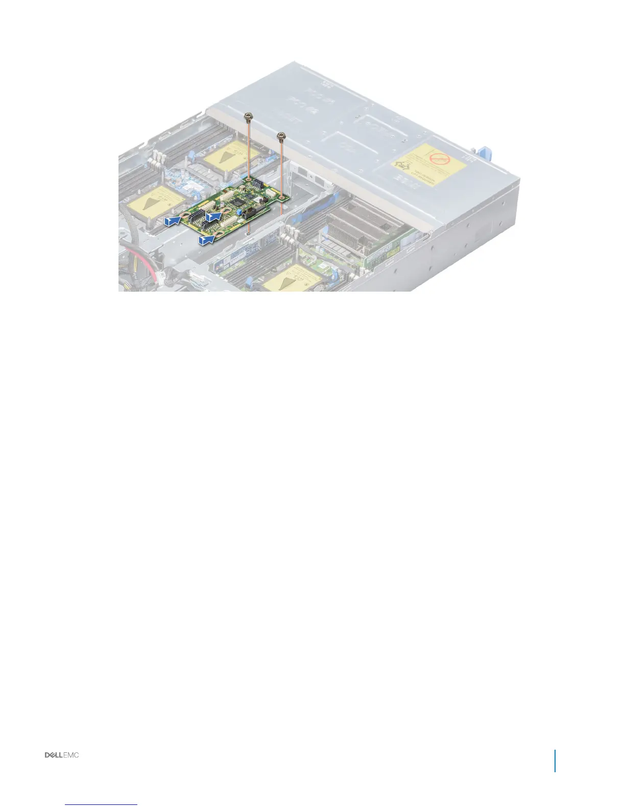
Figure 42. Installing the chassis management board
Next steps
1 Reconnect all the disconnected cables.
2 Install the power interposer board.
3 Install the power supply units.
4 Follow the procedure listed in After working inside your system.
Related links
Installing a power supply unit
Installing the power interposer board
Linking board
The linking board connects the sled to the allotted drives on the backplane.
Removing the linking board
Prerequisites
1 Follow the safety guidelines listed in Safety instructions.
2 Follow the procedure listed in Before working inside your system.
3 Remove the sleds from the enclosure.
4 Remove the fan cage.
Steps
1 Using the Phillips #1 screwdriver, remove the screw that secures the linking board to the enclosure.
2 Lift the linking board out of the enclosure.
3 Disconnect all the attached cables.
Dell PowerEdge C6400 Installation and Service Manual
Installing and removing enclosure components
59