System board
UMA system board connectors
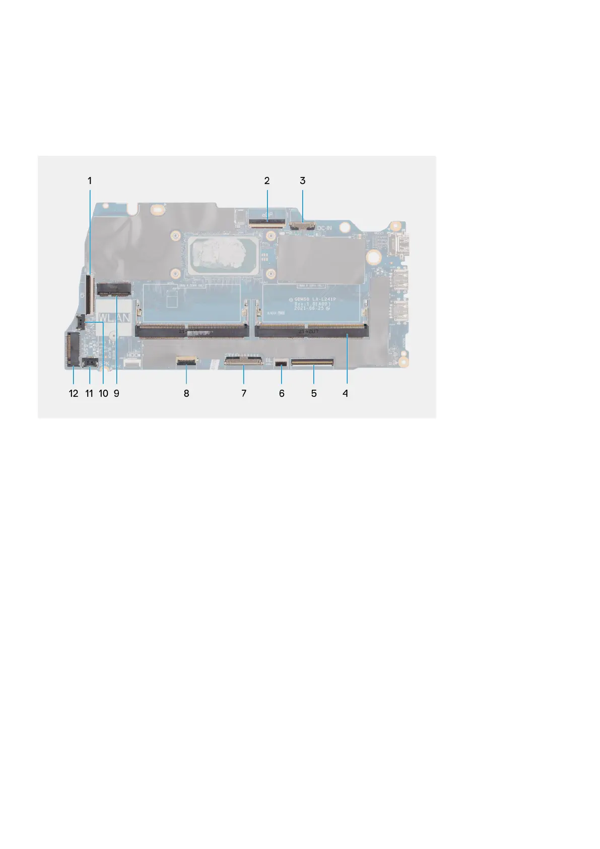
The following image shows the different connectors on the UMA system board.
1. I/O board FFC connector
2. eDP connector
3. DC-in port connector
4. Memory module connectors
5. Keyboard FFC connector
6. Backlit FFC connector
7. Battery connector
8. Touchpad FFC connector
9. Wireless card connector
10. Fan connector
11. Speaker cable connector
12. SSD connector
Removing the UMA system board
Prerequisites
1. Follow the procedure in Before working inside your computer.
2. Remove the base cover.
3. Remove the battery.
4. Remove the memory modules.
5. Remove the M.2 2230 solid-state drive or M.2 2280 solid-state drive, whichever applicable.
6. Remove the wireless card.
7. Remove the fan.
8. Remove the heat sink - UMA or discrete, whichever applicable.
9. Remove the display assembly .
Removing and installing components
65
 Loading...