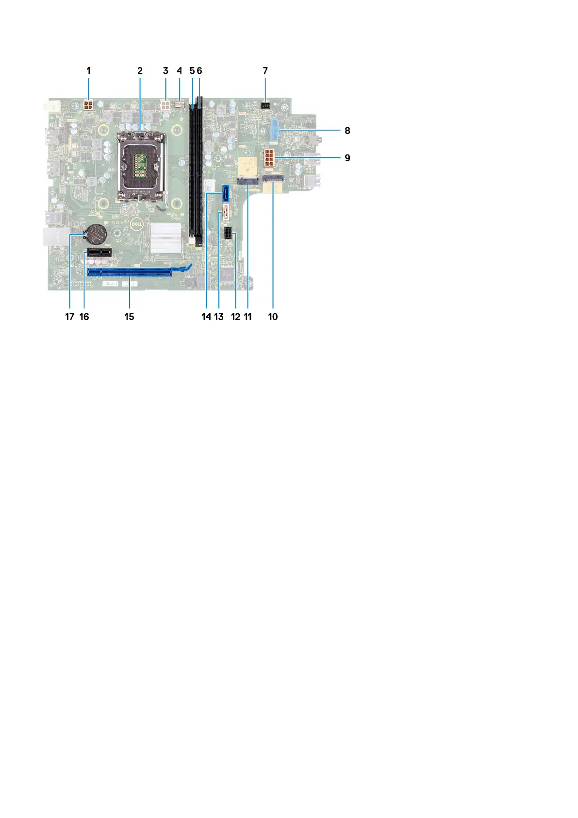
1. processor-power cable connector (ATX CPU1)
2. processor socket
3. processor-power cable connector (ATX CPU2)
4. processor-fan cable connector
5. memory module slot (DIMM1)
6. memory module slot (DIMM2)
7. power-button cable connector
8. media-card reader cable connector
9. system-board power cable connector (ATX SYS)
10. M.2 wireless-card slot
11. M.2 2230/2280 solid-state drive slot
12. hard-drive and optical-drive power cable connector (SATA PWR)
13. optical-drive data cable connector (SATA-3)
14. hard-drive data cable connector (SATA-0, boot drive)
15. PCIe x16 slot (SLOT2)
16. PCIe x1 slot (SLOT1)
17. coin-cell battery socket
The following image(s) indicate the location of the system board and provides a visual representation of the removal procedure.
48
Removing and installing components