EasyManua.ls Logo

Delta 32-100 - Depth of Cut Control.12; Checking and Adjusting Depth of Cut.12; Foot Pedal.12; Adjusting Foot Pedal Cable.12

Delta 32-100
20 pages
Print Icon
To Next Page IconTo Next Page
To Previous Page IconTo Previous Page
Loading...
DEPTH
OF
CUT
CONTROL
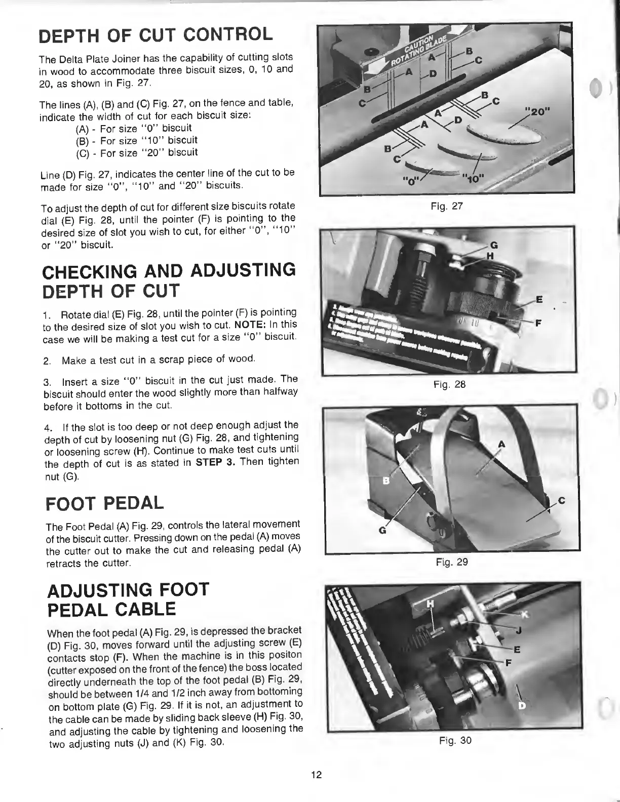
The
Delta
Plate
Joiner
has
the
capability
of
cutting
slots
in
wood
to
accommodate
three
biscuit
sizes,
0,
10
and
20,
as
shown
in
Fig.
27.
The
lines
(A),
(B)
and
(C)
Fig.
27,
on
the
fence
and
table,
indicate
the
width
of
cut
for
each
biscuit
size:
(A)
-
For
size
“0”
biscuit
(B)
-
For
size
“10”
biscuit
(C)
-
For
size
“20”
biscuit
Line
(D)
Fig.
27,
indicates
the
center
line
of
the
cut
to
be
made
for
size
“0”,
“10”
and
“20“
biscuits.
To
adjust
the
depth
of
cut
for
different
size
biscuits
rotate
dial
(E)
Fig.
28,
until
the
pointer
(F)
is
pointing
to
the
desired
size
of
slot
you
wish
to
cut,
for
either
“0”,
“10”
or
“20”
biscuit.
CHECKING
AND
ADJUSTING
DEPTH
OF
CUT
1.
Rotate
dial
(E)
Fig.
28,
until
the
pointer
(F)
is
pointing
to
the
desired
size
of
slot
you
wish
to
cut.
NOTE:
In
this
case
we
will
be
making
a
test
cut
for
a
size
“0”
biscuit.
2.
Make
a
test
cut
in
a
scrap
piece
of
wood.
3.
Insert
a
size
“0”
biscuit
in
the
cut
just
made.
The
biscuit
should
enter
the
wood
slightly
more
than
halfway
before
it
bottoms
in
the
cut.
4.
If
the
slot
is
too
deep
or
not
deep
enough
adjust
the
depth
of
cut
by
loosening
nut
(G)
Fig.
28,
and
tightening
or
loosening
screw
(H).
Continue
to
make
test
cuts
until
the
depth
of
cut
is
as
stated
in
STEP
3.
Then
tighten
nut
(G).
FOOT
PEDAL
The
Foot
Pedal
(A)
Fig.
29,
controls
the
lateral
movement
of
the
biscuit
cutter.
Pressing
down
on
the
pedai
(A)
moves
the
cutter
out
to
make
the
cut
and
releasing
pedal
(A)
retracts
the
cutter.
Fig.
29
ADJUSTING
FOOT
PEDAL
CABLE
When
the
foot
pedal
(A)
Fig.
29,
is
depressed
the
bracket
(D)
F
ig.
30,
moves
forward
until
the
adjusting
screw
(E)
contacts
stop
(F).
When
the
machine
is
in
this
positon
(cutter
exposed
on
the
front
of
the
fence)
the
boss
iocated
directly
underneath
the
top
of
the
foot
pedal
(B)
Fig.
29,
should
be
between
1/4
and
1/2
inch
away
from
bottoming
on
bottom
plate
(G)
Fig.
29.
If
it
is
not,
an
adjustment
to
the
cable
can
be
made
by
sliding
back
sleeve
(H)
Fig.
30,
and
adjusting
the
cable
by
tightening
and
loosening
the
two
adjusting
nuts
(J)
and
(K)
Fig.
30.
Fig.
30
12