Chapter 5 Trial Operation and Tuning ASDA-M
5-10 Revision December, 2014
Please refer to Chapter 3.9.2, Position (PR) Mode Standard Wiring for wiring diagram.
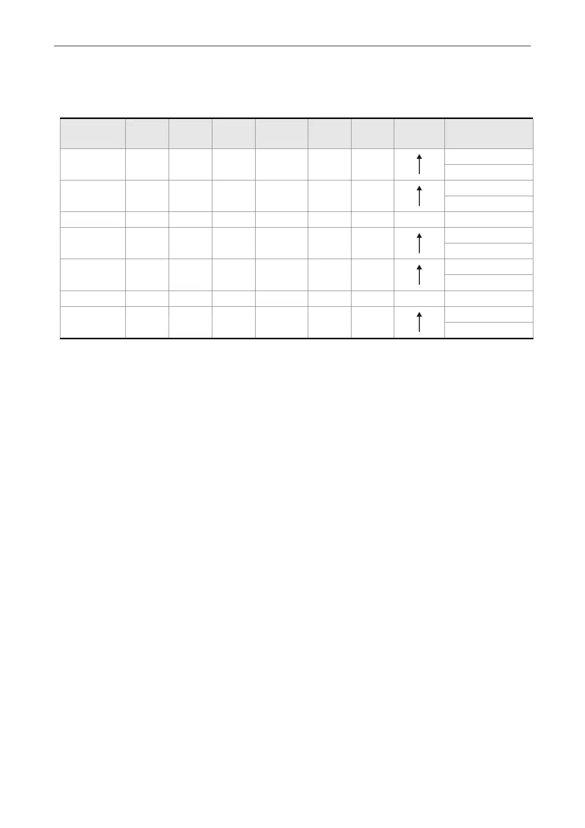
However, since POS2 is not the default digital input, set P2-14 to 113. Please refer to the
table below for 64 sets of register command, POS0~POS5 and the relative parameters.
Position
Command
POS5 POS4 POS3 POS2 POS1 POS0 CTRG
Corresponding
Parameter
P1 0 0 0 0 0 0
P6-00
P6-01
P2 0 0 0 0 0 1
P6-02
P6-03
~ ~
P50 1 1 0 0 1 0
P6-98
P6-99
P51 1 1 0 0 1 1
P7-00
P7-01
~ ~
P64 1 1 1 1 1 1
P7-26
P7-27
0: means DI is OFF
1: means DI is ON
Users can set the 64-set of command value (P6-00~P7-27). The value can be set as the
absolute position command.
 Loading...


