ASDA-M Chapter 6 Control Mode of Operation
Revision December, 2014 6-7
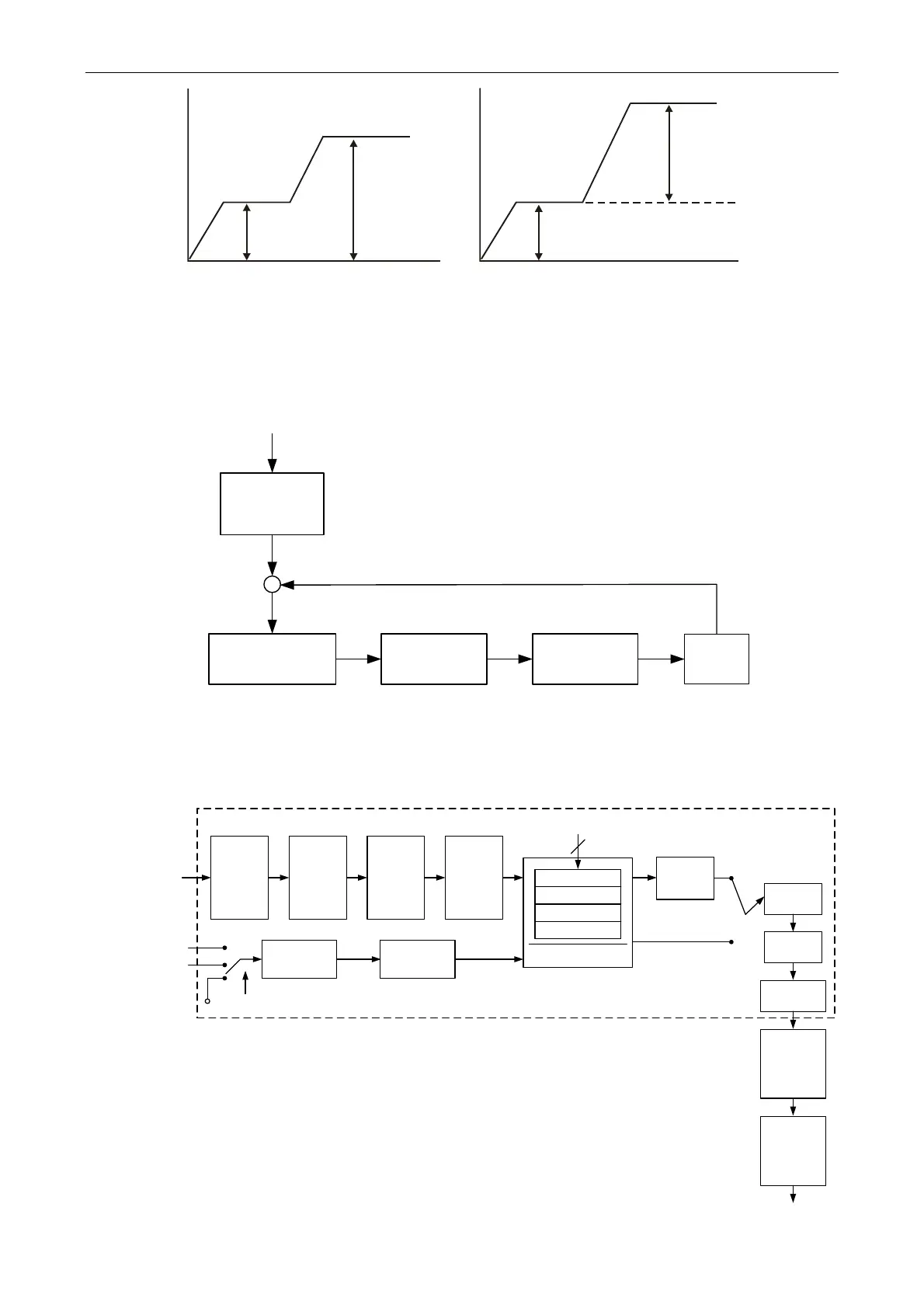
6.2.3 Control Structure of Position Mode
The basic control structure is as the following diagram:
Position
Command
Motor
Speed
Loop
Current
Loop
Position
Control Unit
Position
Command
Unit
For a better control, the pulse signal should be processed and modified through position
command unit. Structure is shown as the diagram below.
Pulse
Signal
CN1
POS5~POS0
CTRG
Command
Register
P6-00
∣
P7-27
Accel/
Decel
Register
P5-20
∣
P5-35
Delay
Time
Register
P5-40
∣
P5-55
Speed
Register
P5-60
∣
P5-75
Counter
S-Curve
Filter
P1-36
1
st
Numerator (P1-44)
2
nd
Numerator (P2-60)
3
rd
Numerator (P2-61)
4
th
Numerator
(P2-62)
Denominator(P1-45)
GNUM0, GNUM1
High speed
Low speed
INHIBIT
Pulse Type
Selection
P1-00
Command
Selection
P1-01
Moving Filter
P1-01
Low-pass
Filter
P1-08
Position
Notch Filter
P1-27
∣
P1-28
Position
Notch Filter
P1-25
∣
P1-26
Position Command Unit
20 turns
10 turns
20 turns
10 turns
Absolute Type Incremental Type
 Loading...


