ASDA-M Chapter 3 Wiring
Revision December, 2014 3-15
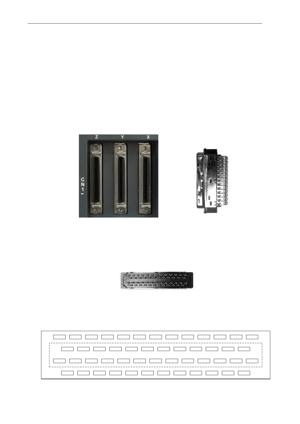
3.3 I/O Signal (CN1) Connection
3.3.1 I/O Signal (CN1) Connector Terminal Layout
In order to have a more flexible communication with the master, 9 programmable Digital
Outputs (DO) and 18 programmable Digital Inputs (DI) are provided. The setting of 6 digital
inputs and 3 digital outputs of each axis provided by ASDA-M, which are parameter
P2-10~P2-15 and parameter P2-18~P2-20 respectively. In addition, the differential output
encoder signal, A+, A-, B+, B-, Z+ and Z-, input of analog torque command, analog
speed/position command and pulse position command are also provided. The followings
are the pin diagrams.
CN1 Connector (female) Side view
Rear view
DI4- DI2-DO1-DO2-DO3- GND NC
MON1 T_REF
VCC /OA /OZ
1
2 24
25
26
27 49
50
NC DO3+ DO2+ DO1+ DI1-
COM+
VDD OB/OBGND
MON2
GND OA
DI5-
PULLHI_S
NC
/HPulse
NC /SIGN
/PULSE PULSE
COM- COM-
PULLHI_P
COM-
OZDI6- DI3-NCNCNC SIGN
/HSIGN V_REF
GND
HSIGN
OCZ
HPulse
The rear wiring terminal of CN1 connector

 Loading...


