ASDA Series Application Note Application Examples
March, 2015 3-7
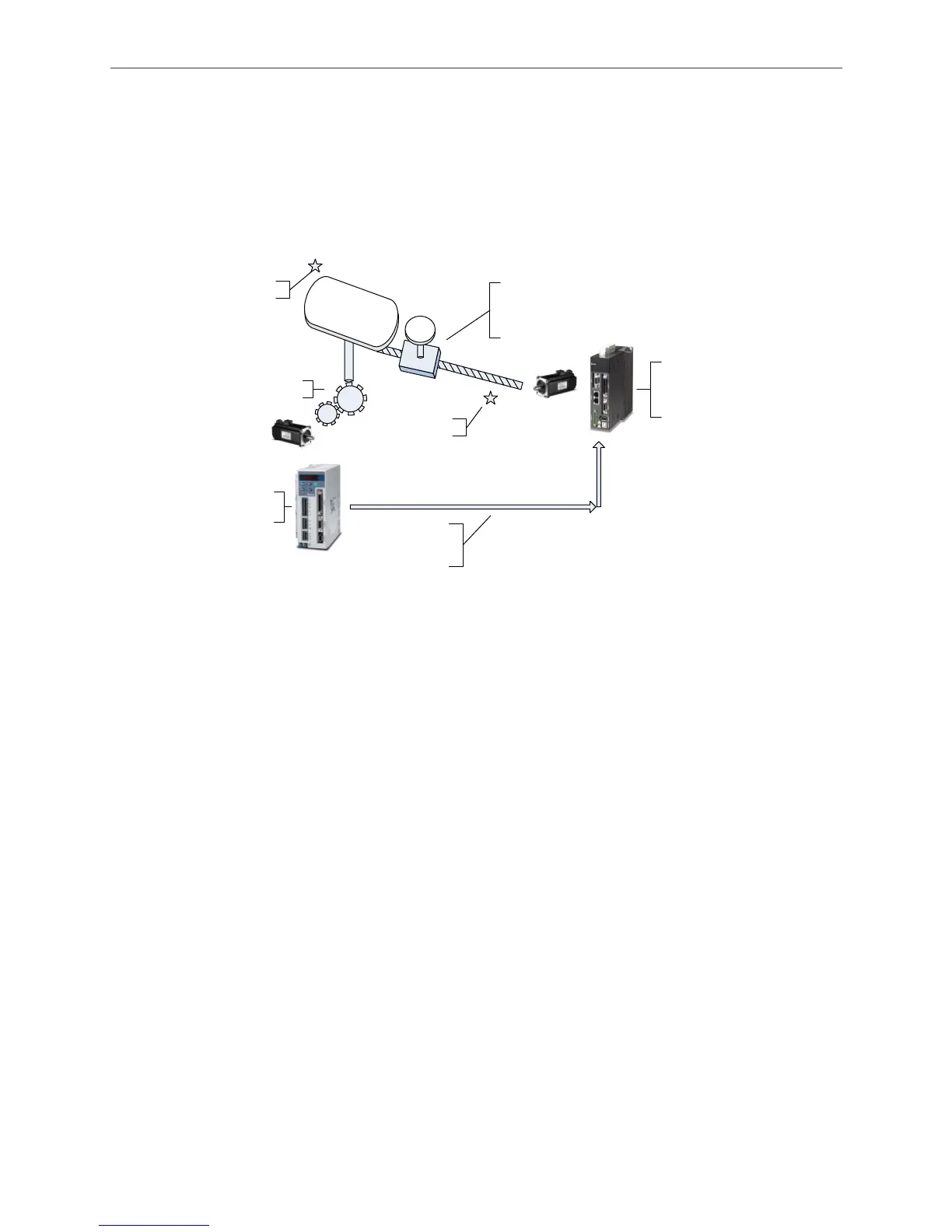
3.1.3.1 System Structure
The master axis used here is an ASDA-A series servo drive and the slave axis used is an
ASDA-A2 series servo drive. There is a decelerator which reduces the speed to 1/5 of the
original speed. The slave axis drives the ball screw via the servo motor. See Figure 3.1.4 system
structure. On master and slave axis, approximation sensors are equipped with the system as the
reference origin for the system.
ASDA-A
series servo drive
Master axis
A2 series servo drive
(slave axis)
1 : 5 decelerator
The platform will
move according to
E-Cam curve from
A2 servo
Pulse signal is sent
to A2 as the master
source signal of the
E-Cam curve
ORG sensor
ORG sensor
operates according to
E-Cam curve
Figure 3.1.4 System Structure
3.1.3.2 Wiring
Regarding the master axis, DI signals that need to connect to the servo drive are DI.SHOM
(search for the origin), DI.ORGP (origin sensor), and DI.CTRG (internal trigger). Among these DI
signals, the function of DI.CTRG is to control the motion of the master axis, making it stop when it
travels one sampling point of the slave axis and allowing the slave axis to complete sampling.
Other signals are for internal use. Since controlling of ON/OFF is not required, actual wiring for
these will be saved, making the I/O wiring easier.
For the slave axis, DI signals that need to connect to the servo drive are mainly DI.SHOM
(search for the origin), DI.ORGP (origin positioning sensor), DI.EV1 (Event 1, for internal trigger),
and DI.CAPTURE (DI7, the trigger point set by the system; setting for register is not required.
When capture function is enabled, this DI will be enabled automatically.) Other DI signals that do
not need to control ON/OFF will be replaced by internal signals without actual wiring.

 Loading...


