ASDA Series Application Note Chapter 4 Application Techniques
March, 2015 4-3
See the example in figure 4.1.1. The output time of two DOs is overlapped. Followings are the
system configuration:
1. Use PR write-in function to write four values, input 1 to input 4 (the timing when DO1
and DO2 is on and off) into data array and regard them as the timing when Compare
outputs. The first compare value (input 1) is the timing to set DO1 on; while the
second value (input 2) is the timing to set DO2 on; the third compare value (input 3) is
the timing to set DO1 off and the fourth one (input 4) is the timing to set DO2 off.
2. When the motor is activated, enable the 1
st
compare function. The compared value is
the first value (input 1) entered into data array. Then, call PR#45. Use Jump function
to call one PR so as to set P4-06 to 0x0001 and to set DO1 on.
3. Then, change the jump path of PR#45 as the next path that will be written into the
value of P4-06.
4. Repeat step 2 ~ 3 to execute the 2
nd
, 3
rd
and 4
th
compare function. When the 2
nd
compare value (input 2) is written into data array, DO2 is on. When the 3
rd
compare
value (input 3) is written to data array, DO1 is off. When the 4
th
compare value (input 4)
is written to data array, DO2 will be off.
See the example in figure 4.1.2. The output time of two DOs is not overlapped. Step 4 is different
in this example. In step 4, when the second compare value (input 2) is written to data array, DO1
is off. When the third compare value (input 3) is written to data array, DO2 is on. And when the
fourth compare value (input 4) is written to data array, DO2 is off.
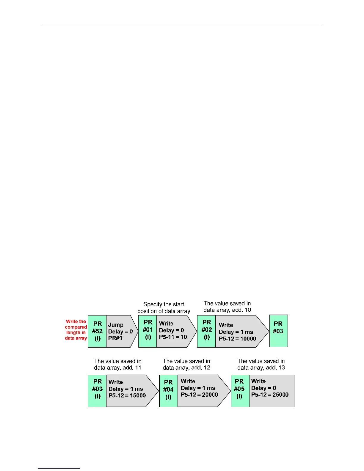
4.1.3 Servo System Setting
PR program
Following describes the PR program when the output time of two DOs is overlapped.

 Loading...


