Introduction of E-Cam Operation ASDA Series Application Note
2-44 March, 2015
curve is stored in data array. When only one E-Cam curve is stored, changing settings of
P5-81 and P5-82 is not required.
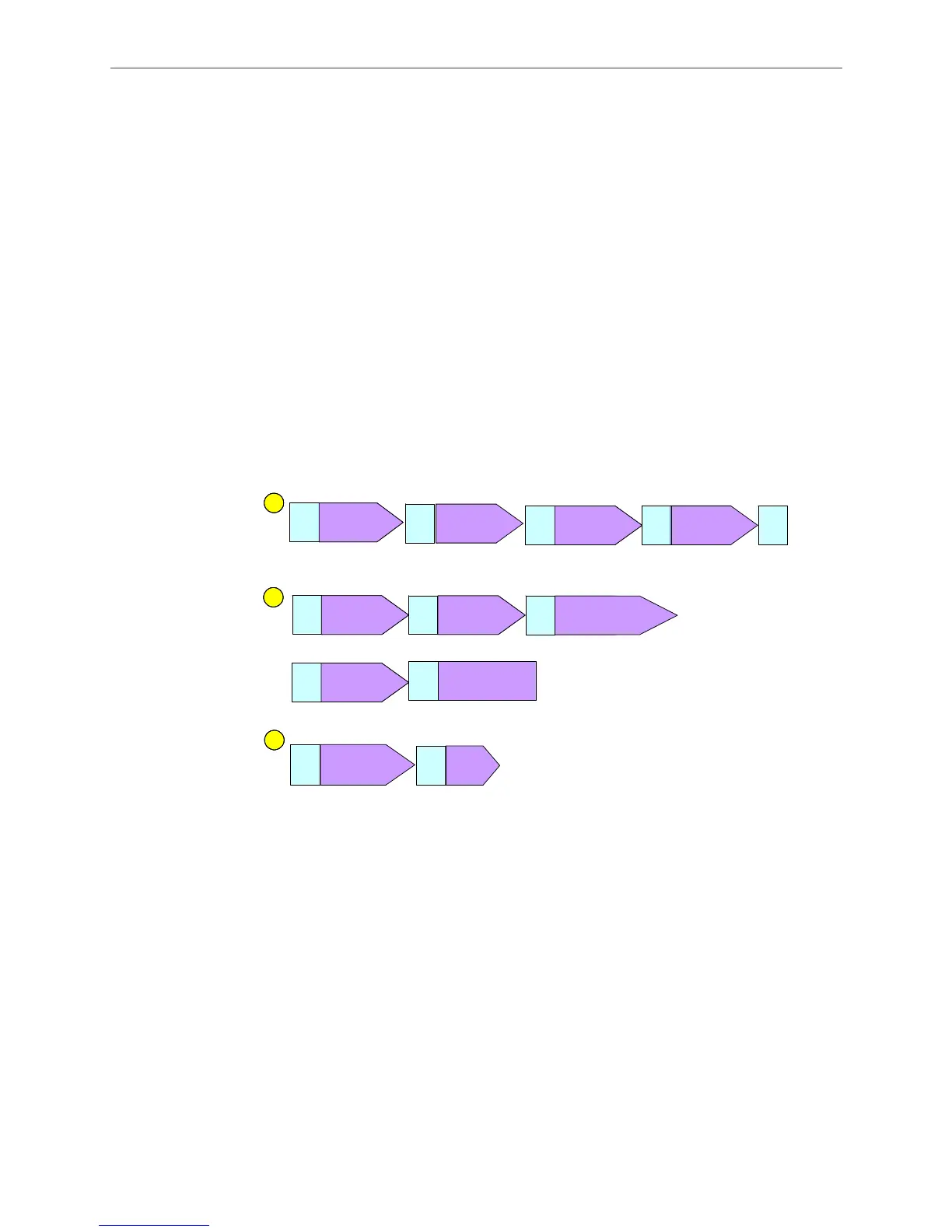
4. Select Based on lead pulse, calculate P5-84 pulse number. Since the moving distance of
the slave axis cannot be changed, which means the traveling distance is fixed, the
system will work out the value required by P5-84 based on the lead pulse. When the
setting is complete, the constant speed area of the slave axis will be consistent with the
master axis.
5. When the above setting is completed, click on Download Table and Burn Table Data to
data array.
2.7.2 Relevant Parameter Settings and Enabling E-Cam Function
When the creation of E-Cam curve is complete, the next step is to enable E-Cam function in
order to have the system work. It is easy to use PR to setup relevant parameters to control
E-Cam. Figure 2.63 is a reference setting; users may edit it to cater to the application
.
Figure 2.63 Using PR command to control E-Cam
PR#0: Homing procedure. Users can specify the homing method according to the mechanism.
Take the mechanism in Figure 2.61 for example. The origin is on the far left. For this type
of mechanism, it has to return to the origin first before taking the next step when system is
started so as to avoid danger.
PR#1: Make sure the slave axis stops at absolute position 0.
PR#2: Specify the disengaging time. Set P5-89 to the same value of P5-84. Then, the slave axis’
operating distance per cycle = the traveling distance per cycle of the E-Cam curve. In this
example, P5-84 = 11555, which is figured out based on slave axis’ lead pulse number by
the ASDA-Soft software tool.
PR
#0
Home X=?
Offset=0
PR#1
1
Homing
procedure
PR
# 0
Home
Offset=0
PR#1
Start homing
procedure when the
system operates for
the first time
1
PR
#12
(I)
PR
# 1
Back to position 0
PR
#2
(I)
Write
DLY = 0 ms
P5-97=0
PR
# 4
(I)
Write
DLY = 0 ms
P5-38=1
Specify Capture address
PR
#2
(I)
PR
# 3
(I)
Set capturing amount
22
PR
#4
(I)
Write
DLY= 1 ms
P5-39=0x0020
PR
# 5
(I)
Write
DLY=0ms
P5-39=0x0020
Stop capture function
PR
#3
(I)
Write
DLY= 0 ms
P5-88=0x0250
PR
# 6
(I)
Write
DLY=1ms
P5-88=0x000A2220
Stop E-Cam
PR
#4
(I)
Write
DLY= 1 ms
P5-39=0x
PR
# 7
(I)
Write
DLY=0ms
P5-39=0x
0021
Enable capture function
PR
#7
(I)
Write
DL Y= 0 ms
P5-88=0x0251
PR
# 8
(I)
Enable E-Cam
Write
DL Y= 0 ms
P5-88=0x000A2221
PR
#12
(I)
PR
# 10
D=0, S=
.
0
rpm
0 PUU, ABS
D=0, S=
100
.
0
rpm
0 PUU, ABS
Move back to 0 after
E-Cam disengaged
(I)(I)
3
D=0, S =1 0.0 rpm
0 PUU, ABS
D=0, S =1 0.0 rpm
0 PUU, ABS
Write
DL Y= 0 ms
P5- =
Write
DL Y= 0 ms
P5-36=0
PR
#12
PR
# 11
Jump
DLY=0
PR# 4
Back to the origin and wait for the next
captured data to engage E-Cam
PR
#4
(I)
Write
DLY= 1 ms
P5-39=0x
PR
# 2
(I)
Write
DLY=0ms
P5-89=P5-84
Setup disengaging time
Homing after
E-Cam disengaged
Enable capture
function & E-Cam
and wait for the
start signal
PR
#2
PR
# 4
Position
Position

 Loading...


